


Wallboard Installation and Maintenance INDeX Wallboard 22
INDeX Contact Centre Modules Page 101
Installation & Maintenance 38HBK00001SCM - Issue 11 (05/01)
RS485 Communication Systems
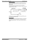
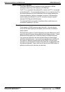
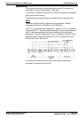
This standard officially allows 30 wallboards to be connected via a RS485
transmission cable of up to 1200 metres to a PC RS485 port.
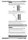
The PC TX+ is connected to the wallboard RX+; similarly, the PC TX- is connected
to the wallboard RX-. The recommended technique is to run a cable from the PC to
the nearest wallboard then from this wallboard to the next nearest wallboard etc.
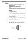
At the last wallboard on the bus it is necessary to connect a 120Ω terminating
resistor between the wallboard RX+ and RX- connections using the supplied
terminated RJ45 Plug and the RJ45 doubler.
The cable specification must include a twisted pair with an overall screen and
characteristic impedance of 100 ohms.
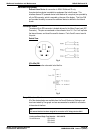
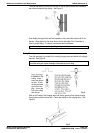
Ground Loops
Proper operation of RS485 requires a signal return path. A third wire should
connect all the system signal grounds together and is most often an additional
shield conductor.
Distributed power systems in industrial applications may have differences in the AC
power line grounds of several volts as measured from location to location. Ground
differences that are greater than 5V RMS can destroy the RS485 transceivers.
Loop currents can exist within the shield conductor because of these voltage
potentials, causing data errors. Loop currents can be minimised by installing 100
ohm resistor in series with the cable shield and the RS485 Line Driver ground
connection or by ensuring that the screen of the cable does not make contact with
the wallboard frame earth. Spurs, which lead off from the main RS485 cable to a
wallboard, should be kept to less than one metre long.