Wallboard Installation and Maintenance INDeX Wallboard 22
INDeX Contact Centre Modules Page 99
Installation & Maintenance 38HBK00001SCM - Issue 11 (05/01)
Periodic Maintenance and Inspection
Cleaning Display Screen
Time periods between cleaning depend upon local conditions and are at the
discretion of the operator. This routine cleaning can be carried out in the normal
way using a damp and/or dry cloth.
Note: This screen is specially coated to reduce reflections and although this coating is very
durable misuse or incorrect cleaning procedures can damage it.
LED Illumination Test Inspection
The purpose of this test is to ensure no LED fails to illuminate and should be
checked annually.
Remove the left-hand end cheek and carefully slide out the logic control board so
that the dip-switches are accessible. Set switch 8 to ON, inspect the LED display
that will run blocks of Green, Red and Yellow across the display. Look for any LEDs
that fail to illuminate.
Return switch 8 to the OFF position to stop this test.
LED Matrix Scanning Inspection
The purpose of this inspection is to ensure the LED matrix is being scanned
correctly. Remove the left-hand end cheek and carefully slide out the logic control
board so that the dip-switches are accessible.
Set switch 7 to ON, Yellow diagonal stripes will run across the display. Check that
these stripes are straight and that Yellow is the only colour displayed. Having
completed this visual inspection return switch 7 to OFF and ensure that all switch
settings comply with system requirements for baud rate and wallboard network
address number. See Section D for dip-switch details.
Serial Connection & Dip-Switch Details
Wallboard Terminal Box RJ45 Connector Pin Out Details
Pin
2 Signal Ground
3 Sign Rx+ Input
4 Sign Tx+ Output
5 Sign Tx- Output
6 Sign Rx- Input
7–
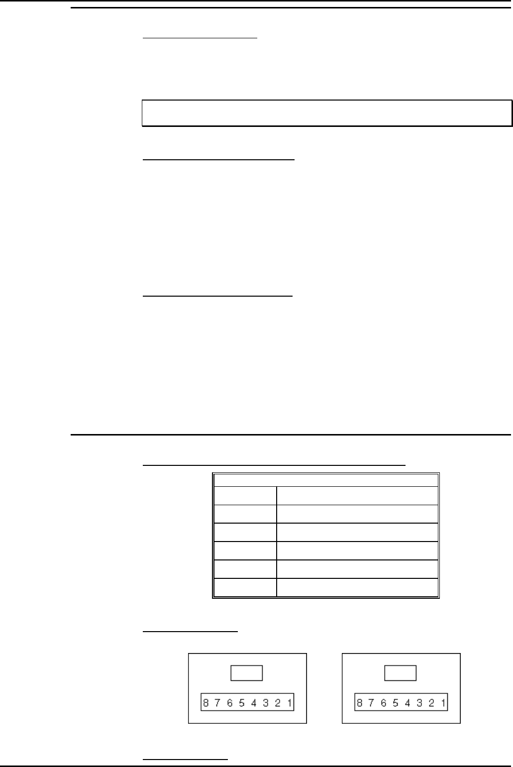
Pin out Connections
Wallboard x RJ45 Socket Wallboard x+1 RJ45 Socket
Pins from 2 to 7 should be connected identically from all RJ45 boxes to all others.
Dip-Switch Details


