5 - 38
5.2 Communication Setup
5.2.3 How to Set Up the Ethernet Connection
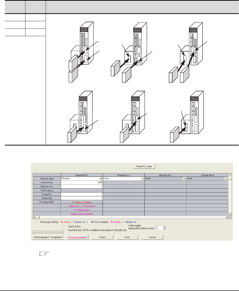
(3) Network parameter setting
Set the network parameters by peripheral devices and write them to the MELDAS C6/C64.
The following shows an example of the parameter setting for GX Developer.
Set the start I/O No. that corresponds to the extension slot to be connected with the Ethernet unit.
When using two extension slots, unit numbers are assigned as shown in the following figures from
1) to 3).
(a) Start I/O No.
(b) Example of GX Developer setting
For details of the parameter setting, refer to the following.
MELDAS C6/C64 NETWORK MANUAL BNP-B2373
Extension
slot
Start I/O
No.
Mounting position of extension unit
EXT1 0200
EXT2 0280
EXT3 0300
EXT2
EXT1
Unit2
Unit1
EXT3
EXT1
EXT2
EXT3
EXT1
(e)When mounted in EXT2 only (f)When mounted in EXT3 only
EXT2
EXT3
(a)When mounted in EXT1 and EXT2 (b)When mounted in EXT1 and EXT3 (c)When mounted in EXT2 and EXT3
(d)When mounted in EXT1 only
Unit2
Unit2
Unit1
Unit1
Unit1
Unit1
Unit1


