


Appendix A
Appendix A-14 Respironics V200 Ventilator Operator’s Manual REF 1057983 A
RS-232 Communications Protocol
Pressure Control
Ventilation Settings
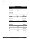
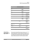
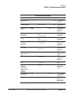
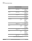
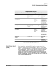
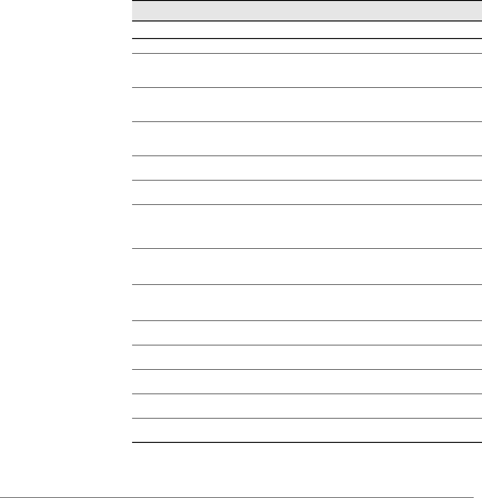
Report (PCVS)
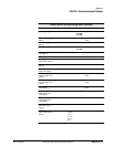
When the ventilator receives PCVS followed by a carriage return, it will respond
by transmitting the information shown in Table A-3: “Pressure Control
Ventilation Settings Report”. The ventilator responds to the PCVS command by
returning a string with a variable length. Fields 2 through 4 define the length
of the message. The last character transmitted is a stop code indicating the
end of the message. The second field indicates the number of characters
between the start and stop codes. The third field indicates the number of
fields between the start and stop codes. The fourth field is the start code,
0x02. The last field in the string is the stop code, 0x03.
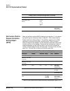
Pressure Control Ventilation Settings Report
Description Example Resolution Range Units Comments
Command Name PCVS N/A N/A N/A
Number of characters
between the start and
stop codes
195 N/A N/A N/A 3 character field
Number of fields
between the start and
stop codes
27 N/A N/A N/A 2 character field
Start Code 0x02 N/A N/A N/A ASCII Start
Transmission
Character (STX)
Time of request 13:45◆ N/A N/A N/A 24 hour clock,
hh:mm◆
Date FEB◆23◆1997◆ N/A N/A N/A 12 character field,
MMM◆DD◆YYYY◆
Current Ventilation
Type
VCV◆◆◆ N/A VCV◆◆◆
PCV◆◆◆
NPPV◆◆
N/A The ventilation
type currently
being used by the
ventilator.
PCV Mode Setting A/C◆◆◆ N/A A/C◆◆◆
SIMV◆◆
CPAP◆◆
N/A
PCV Patient Type ADULT◆ N/A ADULT◆
PED◆◆◆
NEO◆◆◆
PCV Respiratory Rate
Setting
12◆◆◆◆ 1 1 - 150 BPM
PCV Pressure Setting 20◆◆◆◆ 15 - 100cmH
2
O
(hPa)
PCV Inspiratory Time
Setting
1.00◆◆ 0.01 0.1 - 9.9 sec
PCV PEEP Setting 0◆◆◆◆◆ 10 - 35cmH
2
O
(hPa)
PCV Pressure Support
Setting
0◆◆◆◆◆ 10 - 100cmH
2
O
(hPa)
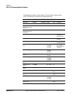
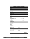
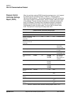
Table A-3: Pressure Control Ventilation Settings Report (Sheet 1 of 3)