


Chapter 6
6-2 Respironics V200 Ventilator Operator’s Manual REF 1057983 A
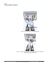
Connecting Additional Equipment
Connecting Serial
Communications
Devices
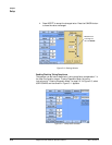
The serial port is designed to transmit data on a one device to one device serial
communications channel. In the connection between the two devices, the
ventilator assumes the “slave” role and responds to commands transmitted to
it via the serial port by the external “master.” The serial communications port
uses a standard RS-232, null modem, pin configuration. The ventilator
assumes the serial communications is set up for:
• 19,200 bits/second baud rate
• 8 data bits
• no parity bit
• 1 stop bit
The ventilator is sent commands that are 4 ASCII characters from the external
device and responds with a fixed format message. The commands and the
responses are specified in Appendix A, “RS-232 Communications Protocol”.
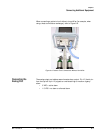
Connecting Remote
Alarm Port
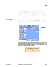
The ventilator is equipped with a remote alarm port enabling ventilator alarm
conditions to be sounded at remote locations away from the ventilator.
Pressing ALARM SILENCE deactivates the remote alarm. The ventilator signals
an alarm using a normally open or normally closed relay contact. The de-
energized state of the relay represents an alarm state (any Medium or High
Priority alarm) and the energized state represents no alarms.
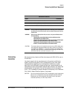
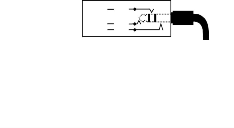
The remote alarm port is a standard ¼ inch, female, phono jack (ring, tip,
sleeve) connector.
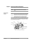
Figure 6-2: Remote Alarm Port
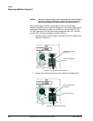
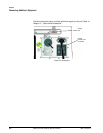
The port is configured to work with the Normally Open (NO), Normally Closed
(NC), and Respironics (LifeCare) systems. Each requires specific cabling
identified in Table 6-1:.
SleeveCommon
TipNC
RingNO
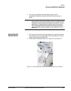
Remote alarm
connector & cable