


MON20/20 Software for Gas Chromatographs User Manual
SEPTEMBER 2010 3-9000-745
7-11
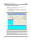
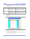
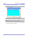
3. Type the starting register value in the Data Addr field.
Note
The data type is set automatically by the Modbus program, based on the specified data
address.
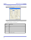
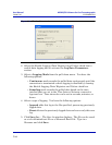
4. In the Quantity field, type the number of registers to be retrieved. The
Modbus program will accept a quantity value of 1 to 2016. The
requested number of registers cannot exceed the amount contained by
the selected message block but you can retrieve a partial block. You
cannot cross a message block boundary.
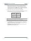
Also, in Standard Modbus mode each register is 16 bits. Therefore,
integers (SHORT) consist of 1 register while floats (FLOAT) and long
integers (LONG) consist of 2 registers.
Note
Boolean registers are not user-defined (for either SIM_2251 or User_Modbus) and
primarily contain alarm flags useful for debugging. To view the contents of Boolean
registers, select the 1 (Read Coil) function code.
Numeric registers for User_Modbus can be user-defined. To view the contents of
Numeric registers, select the 3 (Read Regs) function code.
5. Type the desired repeat count, which is the number of times the
Modbus program should read or set the specified registers before
ceasing transmission, in the Repeat field. The Modbus program will
accept a repeat value of 1 to 9999. A value of –1 produces an infinite
polling loop that can be terminated by clicking Stop.
6. Depending on your intent, select Use template to decode registers or
Use template to decode logs. The Record No field becomes active.
7. Enter the desired record number in the Record No field. To verify
which record number should be entered, consult the Modbus
specifications for your device. For more information on GC Modbus
registers, see Appendix C.