


10
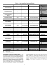
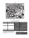
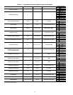
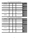
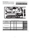
Table 3 — Main Base Board Inputs and Outputs
LEGEND
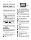
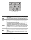
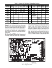
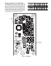
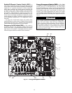
Compressor Protection Module (CPM) — There
is one CPM per compressor. See Fig. 9. The device controls the
compressor contactors, oil solenoid, and loading/unloading the
solenoid. The CPM also monitors the compressor motor tem-
perature, high pressure switch, oil level switch, discharge gas
temperature, oil pressure transducer, motor current, MTA
(must trip amps) setting and economizer pressure transducer
(sizes 175,200,350,400 only). The CPM responds to com-
mands from the MBB (Main Base Board) and sends the MBB
the results of the channels it monitors via the LEN (Local
Equipment Network). The CPM has three DIP switch input
banks, Switch 1 (S1), Switch 2 (S2), and Switch 3 (S3). The
CPM board DIP switch (S1) configures the board for the type
of starter, the location and type of the current transformers and
contactor failure instructions. See Table 4 for description of
DIP switch 1 (S1) inputs. See Appendix D for DIP switch
settings.
DESCRIPTION INPUT/OUTPUT I/O TYPE DISPLAY MODULE POINT NAME
CONNECTION POINT
Pin Notation
Power (24 vac supply) —— —
MBB-J1, MBB-J1A,
MBB-J1B
11 24 vac
12 Ground
Local Equipment Network —— —
MBB-J9A, MBB-J9B,
MBB-J9C, MBBJ9D
+ RS485 Port (D+)
G RS485 Port (Gnd)
- RS485 Port (D-)
Carrier Communication
Network
—— —
MBB-J12
+ RS485 Port (D+)
G RS485 Port (Gnd)
- RS485 Port (D-)
Chilled Water Flow Switch CWFS Switch Cooler Flow Switch, LOCK
MBB-J5B-CH17
17
Demand Limit Switch No. 1 Demand Limit SW1 Switch Limit Switch 1 Status, DLS1 MBB-J4-CH13
Condenser Flow Switch CDFS Switch Condenser Flow Switch, COND 16A MBB-J5A-CH16A
Circuit A Discharge
Pressure Transducer
DPTA Pressure Transducer Discharge Pressure, DP.A
MBB-J7A-CH6
5V +5 vdc Ref.
SSignal
R Return
Circuit B Discharge
Pressure Transducer
DPTB Pressure Transducer Discharge Pressure, DP.B
MBB-J7C-CH8
5V +5 vdc Ref.
SSignal
R Return
Dual Chiller
LWT Thermistor
DUAL 5k Thermistor CHWS Temperature, CHWS MBB-J6-CH3
Dual Set Point Input Dual Set Point Switch Remote Setpoint Switch, DUAL MBB-J4-CH12
Heat/Cool Switch HC_SW Switch Heat/Cool Select Contact, HC_SW
MBB-J4-CH14
Entering Water Thermistor EWT 5k Thermistor Cooler Entering Fluid, EWT MBB-J6-CH2
Leaving Water Thermistor LWT 5k Thermistor Cooler Leaving Fluid, LWT MBB-J6-CH1
Condenser Entering Water
Thermistor
CEWT 5k Thermistor Condenser Entering Fluid, CEWT MBB-J6-CH5
Condenser Leaving Water
Thermistor
CLWT 5k Thermistor Condenser Leaving Fluid, CLWT MBB-J6-CH4
External Chilled
Water Pump Interlock
PMPI Switch Electrical Box Interlock, ELEC MBB-J4-CH15A
Circuit A Suction
Pressure Transducer
SPTA Pressure Transducer Suction Pressure, SP.A
MBB-J7B-CH7
5V +5 vdc Ref.
SSignal
R Return
Circuit B Suction
Pressure Transducer
SPTB Pressure Transducer Suction Pressure, SP.B
MBB-J7D-CH9
5V +5 vdc Ref.
SSignal
R Return
Unit Status Remote Contact-Off-Enable Switch On/Off Remote Switch, ONOF MBB-J4-CH11
Alarm Relay ALM R Relay Alarm Relay Output, ALRM MBB-J3-CH24
Alert Relay ALT R Relay Alert Relay Output, ALRT MBB-J3-CH25
Cooler Pump Relay 1 PMP1 Contactor Cooler Pump 1, CPUMP_1 MBB-J2A-CH19
Cooler Pump Relay 2 PMP2 Contactor Cooler Pump 2, CPUMP_2 MBB-J2A-CH20
Condenser Pump Relay CPMP Contactor Condenser Pump, COND_PMP MBB-J2C-CH22
Pump #1 Interlock
Pump #2 Interlock
PMP_1
PMP_2
Switch Cooler Pump Run Status, PUMP MBB-J5C-CH18
I/O — Input or Output
LWT — Leaving Water Temperature