


17
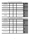
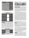
Table 9 — Energy Management Module (EMM) Inputs and Outputs
* A field-supplied 1/2 watt 250 ohm resistor is required across terminals TB6-1,2 (CH6) and/or TB6-3, 4 (CH5).
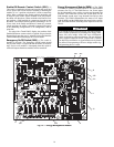
Local Equipment Network — Information is trans-
mitted between modules via a 3-wire communication bus or
LEN (Local Equipment Network). External connection to the
LEN bus is made at TB3.
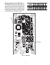
Board Addresses — All boards (except the Main Base
Board and Energy Management Module Board) have
8-position DIP switches.
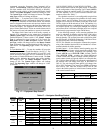
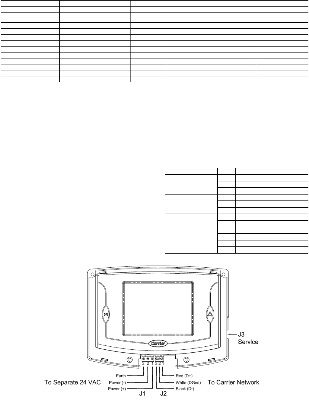
Touch Pilot™ Display — The Touch Pilot display port
connections are shown in Table 10. Wiring is shown in Fig. 13.
Control Module Communication
RED LED — Proper operation of the control boards can be
visually checked by looking at the red status LEDs (light-
emitting diodes). When operating correctly, the red status
LEDs will blink in unison at a rate of once every 2 seconds. If
the red LEDs are not blinking in unison, verify that correct
power is being supplied to all modules. Be sure that the Main
Base Board (MBB) is supplied with the current software. If
necessary, reload current software. If the problem still persists,
replace the MBB. A red LED that is lit continuously or blink-
ing at a rate of once per second or faster indicates that the board
should be replaced.
GREEN LED — All boards have a green LEN (SIO) LED
which should be blinking whenever power is on. If the LEDs
are not blinking as described check LEN connections for
potential communication errors at the board connectors. See
input/output Tables 3-10 for LEN connector designations. A
3-wire bus accomplishes communication between modules.
These 3 wires run in parallel from module to module. The J9A
connector on the MBB provides communication directly to the
Navigator™ display module.
YELLOW LED — The MBB has one yellow LED. The
Carrier Comfort Network
®
(CCN) LED will blink during times
of network communication.
Table 10 — Touch Pilot™ Display Port
Connections
INPUT/OUTPUT DESCRIPTION I/O TYPE DISPLAY MODULE POINT NAME CONNECTION POINT
4-20 mA Demand Limit 4-20 mA Demand Limit 4-20 mA* Limit 4-20 mA Signal, DMD EMM-J7B-CH6
4-20 mA Temperature
Reset/Cooling Setpoint
4-20 mA Temperature Reset/
Cooling Set point
4-20 mA*
Reset/Setpnt 4-20 mA Signal, RSET
EMM-J7A-CH5
Demand Limit SW2 Demand Limit Step 2 Switch Input Switch Limit Setpoint 2, DLS2 EMM-J4-CH9
Ice Done Ice Done Switch Switch Input Ice Done Storage Switch, ICE.D EMM-J4-CH11A
Occupancy Override Occupied Schedule Override Switch Input Occupied Override Switch, OCCS EMM-J4-CH8
Remote Lockout Switch Chiller Lockout Switch Input Remote Interlock Switch, RLOC EMM-J4-CH10
SPT Space Temperature Thermistor 10k Thermistor Optional Space Temp, SPT EMM-J6-CH2
% Total Capacity Percent Total Capacity Output 0-10 vdc Chiller Capacity Signal, CATO EMM-J8-CH7
RUN R Run Relay Relay Running Status, RUN EMM-J3-CH25
SHD R Shutdown Relay Relay Shutdown Indicator State, SHUT EMM-J3-CH24
CA_S Run Status for Circuit A Relay Compressor A Run Status, Q_RUN_A EMM-J2A-CH17
CB_S Run Status for Circuit B Relay Compressor B Run Status, Q_RUN_B EMM-J2A-CH18
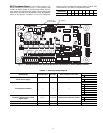
CONNECTOR PIN FUNCTION
J1 (Power)
124VAC +
224VAC -
3 Earth Ground
J2 (COM1)
1 RS485 Port (D+)
2 RS485 Port (GND)
3 RS485 Port (D-)
J3 (RJ11)
124VAC (+)
2 RS485 Port (D+)
3 RS485 Port (GND)
4 Unused (no connect)
5 RS485 Port (D-)
624VAC(-)
Fig. 13 — Touch Pilot™ Display Wiring