


42
Set this variable to 2 for stand-alone units that are not con-
nected to a CCN. With this configuration, daylight saving time
and holiday determination will be done without broadcasting
through the bus. This variable can only be changed when using
the Touch Pilot display, ComfortVIEW™ software, or
Network Service Tool. This variable cannot be changed with
the Navigator display.
To configure this option with the Touch Pilot display:
BROADCAST ACKNOWLEDGER — This configuration
defines if the chiller will be used to acknowledge broadcast
messages on the CCN bus. One broadcast acknowledger is
required per bus, including secondary buses created by the use
of a bridge. This variable can only be changed with the Touch
Pilot display, ComfortVIEW software, or Network Service
Tool. This variable cannot be changed with the Navigator
display.
To configure this option with the Touch Pilot display:
Alarm Control
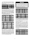
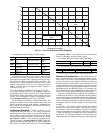
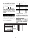
ALARM ROUTING CONTROL — Alarms recorded on the
chiller can be routed through the CCN. To configure this op-
tion, the ComfortLink control must be configured to determine
which CCN elements will receive and process alarms. Input for
the decision consists of eight digits, each of which can be set to
either 0 or 1. Setting a digit to 1 specifies that alarms will be
sent to the system element that corresponds to that digit. Set-
ting all digits to 0 disables alarm processing. The factory de-
fault is 00000000. See Fig. 26. The default setting is is based
on the assumption that the unit will not be connected to a net-
work. If the network does not contain a ComfortVIEW, Com-
fortWORKS
®
, TeLink, DataLINK™, or BAClink module, en-
abling this feature will only add unnecessary activity to the
CCN communication bus.
This option can be modified by the Touch Pilot display. It
cannot be modified with the Navigator display.
Typical configuration of the Alarm Routing variable is
11010000. This Alarm Routing status will transmit alarms to
ComfortVIEW software, TeLink, BAClink, and DataLINK.
To configure this option with the Touch Pilot display:
ALARM EQUIPMENT PRIORITY — The ComfortVIEW
device uses the equipment priority value when sorting alarms
by level. The purpose of the equipment priority value is to de-
termine the order in which to sort alarms that have the same
level. A priority of 0 is the highest and would appear first when
sorted. A priority of 7 would appear last when sorted. For ex-
ample, if two chillers send out identical alarms, the chiller with
the higher priority would be listed first. The default is 4. This
variable can only be changed when using the Touch Pilot dis-
play, ComfortVIEW software, or Network Service Tool. This
variable cannot be changed with the Navigator™ display. To
configure this option with the Touch Pilot™ display:
COMMUNICATION FAILURE RETRY TIME — This vari-
able specifies the amount of time that will be allowed to elapse
between alarm retries. Retries occur when an alarm is not
acknowledged by a network alarm acknowledger, which may
be either a ComfortVIEW software or TeLink. If acknowledge-
ment is not received, the alarm will be re-transmitted after the
number of minutes specified in this decision. This variable can
only be changed with the Touch Pilot display, ComfortVIEW,
or Network Service Tool. This variable cannot be changed with
the Navigator display. To configure this option with the Touch
Pilot display:
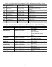
DISPLAY NAME PATH LINE NO. VALUE
Activate Config BRODEFS 1
Range = 0 to 2
Default = 2
DISPLAY NAME PATH LINE NO. VALUE
Broadcast acknowledger Config Ctlt-ID 10 Yes
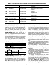
DISPLAY NAME PATH LINE NO. VALUE
Alarm Routing
Control
Config ALARMDEF 1 Default = 00000000
DISPLAY NAME PATH LINE NO. VALUE
Alarm Equipment
Priority
Config ALARMDEF 2
Range = 0 to 7
Default = 4
DISPLAY NAME PATH LINE NO. VALUE
Comm Failure
Retry Time
Config ALARMDEF 3
Range =
1 to 240 minutes
Default =
10 minutes
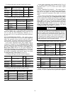
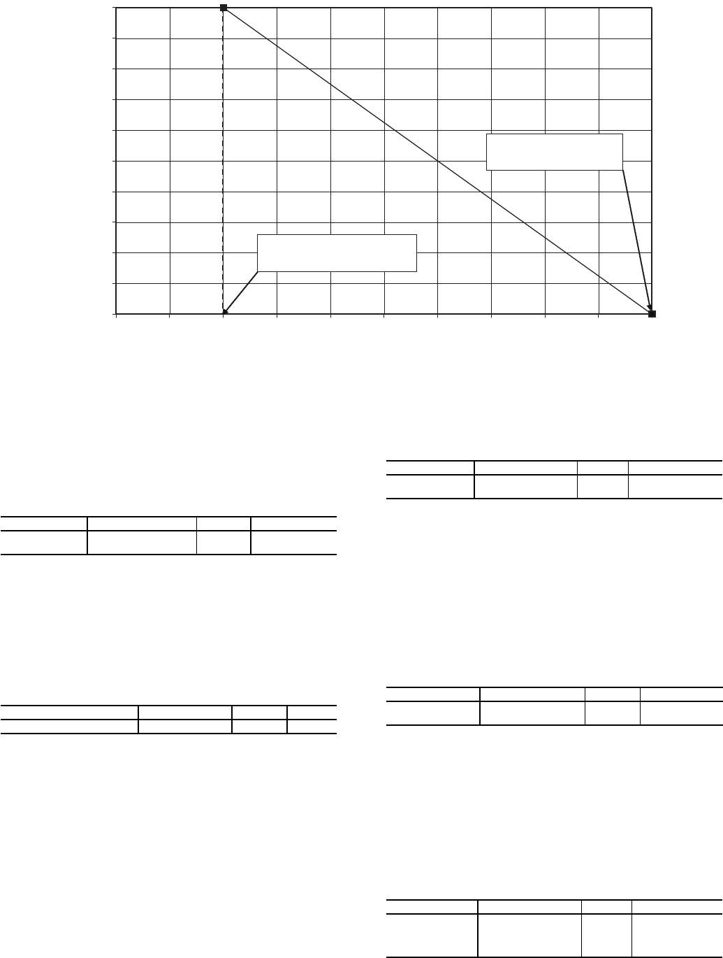
200
0
400
600
800
1000
1200
1400
1600
1800
2000
0
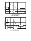
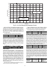
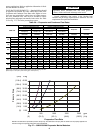
mA Signal
Compressor Current
mA For 100%
Demand Limit,
DMMX
mA For 0% Demand Limit,
DMZE
24 6
8
10 12
14
16 18 20
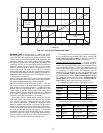
Fig. 25 — 4 to 20 mA Demand Limit (Compressor Current)
a30-4832