


54
OPERATION
Sequence of Operation —
With a command to start
the chiller, the cooler and condenser pumps will start. After
verifying water flow, the control will monitor the entering and
leaving water temperatures. If the need for mechanical cooling
is determined, the control decides which circuit and compres-
sor to start. The control will start the required compressor com-
pletely unloaded. The control will continue to load this circuit
by moving the slide valve to satisfy cooling requirements.
Once fully loaded, the control will start an additional circuit to
satisfy the load as required. Shutdown of each circuit under
normal conditions occurs in the opposite sequence to loading.
Once the circuit is fully unloaded the compressor is shut off
and the EXV will close completely.
Dual Chiller Sequence of Operation — With a
command to start the chiller, the master chiller determines
which chiller will become the lead chiller based on the configu-
ration of Lead Lag Select, LLBL and Lead/Lag Balance Da-
ta, LLBD. The lead chiller is always started first and the lag
chiller is held at zero percent capacity by the master chiller
forcing the lag demand limit value to 0%. If Lead Pulldown
Time (Lead Pulldown Time, LPUL) has been configured, the
lead chiller will continue to operate alone for that specified
time. After the Lead Pulldown Time timer has elapsed and
when the lead chiller is fully loaded, either all available com-
pression is on or at the master demand limit value, then the lag
start timer (Lag Start Timer, LLDY) is initiated. When the
pulldown timer and lag start timer has elapsed and the Com-
bined Leaving Chilled Water Temperature is more than 3° F
(1.7° C) above the set point, then the lag chiller is started. If the
lag chiller’s water pump was not started when the machines
went into occupied mode, the lag chiller water pump will be
started. The lag chiller will start with the master chiller forcing
the lag chiller demand limit value (LAG_LIM) to the master’s
demand limit value. If lead/lag capacity balance is selected,
once the lag chiller has started, the master shall try to keep the
difference in capacity between lead and lag less than 20%. The
master shall then be responsible for water loop capacity
calculation, and will determine which chiller, the lead or lag,
will increase or decrease capacity. When the load reduces, the
lag chiller will be the first chiller to unload. To accomplish this,
the lead chiller set point is decreased by 4° F (2.2° C) until the
lag chiller unloads.
PUMP OPERATION — For parallel chiller pump operation,
the lead chiller’s water pump will be started. The lag chiller’s
water pump will be maintained off if Lag Unit Pump Control,
LAGP=0. The internal algorithm of lead chiller will control ca-
pacity of the lead chiller.
For series chiller operation, the pump is always controlled
by the master chiller.
Operating Modes — Operating modes are override
modes that affect normal operation of the equipment. More
than one operating mode can be in effect at the same time.
Some operating modes have corresponding capacity control
overrides in the Capacity Control Overrides section on
page 43.
For the Touch Pilot display, the status of the operating
modes can be found in the MODES submenu, which is under
the STATUS menu. Each operating mode and its status (Yes =
active, No = inactive) is listed.
For the Navigator display, the status of the operating modes
can be found in the MODE submenu under the OPERATING
MODES menu. The 6 top priority operating modes are dis-
played in MD01 through MD06. To view the modes with the
Navigator display:
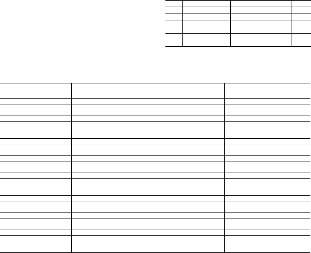
See Table 37 for a list of operating modes.
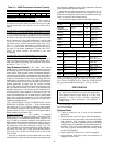
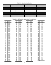
Table 37 — 30XW Operating Modes
ITEM ITEM EXPANSION PATH VALUE
MD01 First Active Mode Operating modes MODE 0-32
MD02 Second Active Mode Operating modes MODE 0-32
MD03 Third Active Mode Operating modes MODE 0-32
MD04 Fourth Active Mode Operating modes MODE 0-32
MD05 Fifth Active Mode Operating modes MODE 0-32
MD06 Sixth Active Mode Operating modes MODE 0-32
NAVIGATOR OPERATING
MODE NUMBER
NAVIGATOR EXPANSION TOUCH PILOT DISCRIPTION
TOUCH PILOT
LINE NUMBER
TOUCH PILOT
VALUE
01 Startup Delay in Effect Startup Delay in Effect 2 Yes/No
02 Second Setpoint in Use Second Setpoint in Use 3 Yes/No
03 Reset in Effect Reset in Effect 4 Yes/No
04 Demand Limit Active Demand Limit Active 5 Yes/No
05 Ramp Loading Active Ramp Loading Active 6 Yes/No
06 Cooler Heater Active Cooler Heater Active 7 Yes/No
07 Cooler Pumps Rotation Cooler Pumps Rotation 8 Yes/No
08 Pump Periodic Start Pump Periodic Start 9 Yes/No
09 Night Low Noise Active Night Low Noise Active 10 Yes/No
10 System Manager Active System Manager Active 11 Yes/No
11 Mast Slave Ctrl Active Mast Slave Active 12 Yes/No
12 Auto Changeover Active Auto Changeover Active 13 Yes/No
13 Free Cooling Active Free Cooling Active 14 Yes/No
14 Reclaim Active Reclaim Active 15 Yes/No
15 Electric Heat Active Electric Heat Active 16 Yes/No
16 Heating Low EWT Lockout Heating Low EWT Lockout 17 Yes/No
17 Condenser Pumps Rotation Condenser Pumps Rotation 18 Yes/No
18 Ice Mode in Effect Ice Mode in Effect 19 Yes/No
19 Defrost Active on Cir A Defrost Active on Cir A 20 Yes/No
20 Defrost Active on Cir B Defrost Active on Cir B 21 Yes/No
21 Low Suction Circuit A Low Suction Circuit A 22 Yes/No
22 Low Suction Circuit B Low Suction Circuit B 23 Yes/No
24 High DGT Circuit A High DGT Circuit A 25 Yes/No
25 High DGT Circuit B High DGT Circuit B 26 Yes/No
27 High Pres Override Cir A High Pres Override Cir A 28 Yes/No
28 High Pres Override Cir B High Pres Override Cir B 29 Yes/No
30 Low Superheat Circuit A Low Superheat Circuit A 31 Yes/No
31 Low Superheat Circuit B Low Superheat Circuit B 32 Yes/No