


60
The EXV control logic has several overrides, which are also
used to control the position of the EXV.
• Approach between SST and LWT
• Maximum Operating Pressure (MOP)
Approach
— If the approach (pinch), which is the difference
between leaving fluid temperature and saturated suction tem-
perature, is equal to or less than the pinch set point then the
EXV will not open any further even though discharge super-
heat set point is not met. Pinch set point is calculated using
suction superheat, discharge superheat and pinch offset. Pinch
offset is used to adjust calculated pinch set point do to accuracy
of transducers and thermistors.
MOP
— The EXV is also used to limit cooler saturated suction
temperature to 55 F (12.8 C). This makes it possible for the
chiller to start at higher cooler fluid temperatures without over-
loading the compressor. This is commonly referred to as MOP
(maximum operating pressure). If the SST is equal to or greater
than the MOP set point then the MBB will try to control the
EXV position to maintain the MOP set point.
The discharge superheat leaving the compressor is main-
tained between approximately 18 and 25 F (10 and 14 C), or
less. Because EXV status is communicated to the Main Base
Board (MBB) and is controlled by the EXV modules, it is pos-
sible to track the valve position. The unit is then protected
against loss of charge and a faulty valve. During initial start-up,
the EXV is fully closed. After an initialization period, valve
position is tracked by the EXV module by constantly monitor-
ing the amount of valve movement.
ECONOMIZER EXV CONTROL — The economizer EXV
is controlled by the circuit EXV board. There is an economizer
gas temperature thermistor and economizer pressure transducer
located in the line, which runs from the economizer assembly to
the compressor. The economizer pressure is converted to satu-
rated temperature and is used to calculate economizer superheat.
Economizer superheat equals economizer temperature minus
saturated economizer temperature. The economizer EXV only
operates during normal conditions when the capacity of the
circuit is greater than 70%. Once the capacity of the circuit is
greater than 70% the MBB will start controlling the economizer
EXV to maintain economizer superheat set point, which is ap-
proximately 8° to 12° F (4.4° to 6.7° C). If the circuit capacity is
less than 70%, the economizer EXV will be closed.
The economizer EXV has one override. If the discharge gas
temperature exceeds 195 F (90.6 C) the economizer EXV will
start to open. The EXV will be controlled to maintain discharge
gas temperature at approximately 195 F (90.6 C).
If it appears that main EXV or economizer EXV is not
properly controlling circuit operation to maintain correct super-
heat, there are a number of checks that can be made using test
functions and initialization features built into the microproces-
sor control. See the Service Test section to test EXVs.
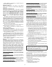
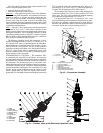
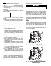
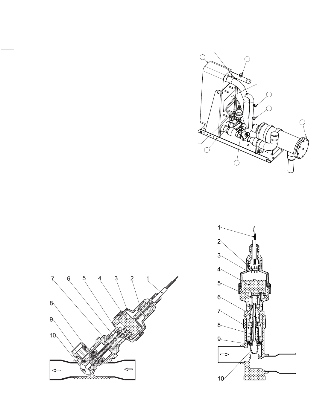
Fig. 42 — Economizer Assembly
MAIN EXV CONNECTOR
ECONOMIZER
EXV CONNECTOR
NAME PLATE
1
6
4
5
1
2
3
LEGEND
EXV — Electronic Expansion Valve
1—Fuse Plug Adaptor
2—High Flow Access Fitting
3—Filter Drier
4—Main Expansion Valve
5—Economizer Expansion Valve
6—Brazed Plate Heat Exchanger
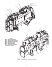
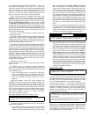
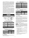
Fig. 43 — Cutaway Views of the Electronic Expansion Valve
1. Cable
2. Glass Seal
3. Motor Housing
4. Stepper Motor
5. Bearing
6. Lead Screw
7. Insert
8. Valve Piston
9. Valve Seat
10. Valve Port
a30-4241