


16
Enable-Off-Remote Contact Switch (SW1) —
This switch is installed in all units and provides the owner and
service person with a local means of enabling or disabling the
machine. It is a 3-position switch and it is used to control the
chiller. When switched to the Enable position, the chiller will
be under its own control. When switched to the Off position,
the chiller will shut down. When switched to the Remote Con-
tact position, a field-installed dry contact can be used to start
the chiller. The contacts must be capable of handling a 24-vac,
50-mA load. In the Enable and Remote Contact (dry contacts
closed) positions, the chiller is allowed to operate and respond
to the scheduling configuration, CCN configuration, and set
point data.
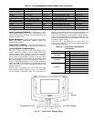
For units with a Touch Pilot™ display, the position of the
Enable/Off/Remote contact switch is ignored except when the
Remote Mode operating type is selected. Refer to the Machine
Control Methods section on page 20 for more details.
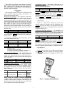
Emergency On/Off Switch (SW2) — This switch is
installed in all units. The Emergency On/Off switch should
only be used when it is required to shut the chiller off immedi-
ately. Power to all modules is interrupted when this switch is
off and all outputs from these modules will be turned off.
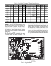
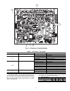
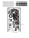
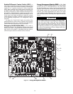
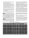
Energy Management Module (EMM) — The EMM
is available as a factory-installed option or as a field-installed
accessory. See Fig. 12. The EMM receives 4 to 20 mA inputs
for the temperature reset, cooling set point and demand limit
functions. The EMM also receives the switch inputs for the
field-installed second stage 2-step demand limit and ice done
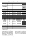
functions. The EMM communicates the status of all inputs
with the MBB, and the MBB adjusts the control point, capacity
limit, and other functions according to the inputs received. See
Table 9.
CAUTION
Care should be taken when interfacing with other manufac-
turer’s control systems due to possible power supply differ-
ences, full wave bridge versus half wave rectification,
which could lead to equipment damage. The two different
power supplies cannot be mixed. ComfortLink™ controls
use half wave rectification. A signal isolation device should
be utilized if incorporating a full wave bridge rectifier sig-
nal generating device is used.
Fig. 12 — Energy Management Module
221
221
221
221
100K
100K
100K
100K
100K
CH
17
CH
17
CH
16
CH
CH
18
CH
19
CH
20
CH
22
CH
21
CH
23
24 VAC
12 11
CH
11b
CH
12
CH
13
CH
14
CH
15
CH
1
CH
2
CH
3
CH
4
CH 5
CH 6
CH 7
SIO LEN
+ G -
+ G -
SIO LEN
J8
J7B
J7A
J6
J5
J4J3J2B
J2A
J1
J9A
J9B
a30-4911