


46
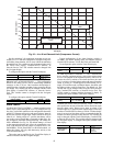
Table 34 — 30XW Compressor Nominal Capacity
Override #59: Circuit A Low Oil Level
Override #60: Circuit B Low Oil Level — This override is
only effective when the circuit is not running. The override will
prevent the circuit from starting up with a low oil level. If this
override occurs three times, the low oil level alarm will be
tripped.
Override #62: Circuit A High Motor Temperature Override
Override #63: Circuit B High Motor Temperature Override
— This override prevents the compressor motor temperature
from rising above the high temperature limit, but still allows
the chiller to run close to the high temperature limit by unload-
ing the compressor. If the motor temperature is greater than
214 F (101.1 C), the compressor will not load. This override
will remain active until the temperature drops below 214 F
(101.1 C). If the motor temperature is greater than 225 F
(107.2 C) for 60 seconds, the circuit capacity will decrease by
one stage. If the motor temperature is greater than 228 F
(108.9), the circuit capacity will decrease by one stage
immediately.
Override #66: Circuit A High Discharge Gas Override
Override #67: Circuit B High Discharge Gas Override —
When the temperature is above the limit minus 2° F (1.1° C) in-
crease in capacity will not be allowed. This override will re-
main active until the discharge gas temperature drops below
the limit by –3° F (–1.7° C).
Head Pressure Control — The Main Base Board
(MBB) uses the saturated condensing temperature input from
the discharge pressure transducer to control the head pressure
control signal. Head pressure control is maintained through a
calculated set point which is automatically adjusted based on
actual saturated condensing and saturated suction temperatures
so that the compressor(s) is (are) always operating within the
manufacturer’s specified envelope. The control will automati-
cally reduce the unit capacity as the saturated condensing tem-
perature approaches an upper limit. See capacity overrides
#16-18. The control will indicate through an operating mode
that high ambient unloading is in effect. If the saturated con-
densing temperature in a circuit exceeds the calculated maxi-
mum, the circuit will be stopped. For these reasons, there are
no head pressure control methods or set points to enter. The
control will modulate the 0 to 10v head pressure control output
signal when condensing temperature is below the minimum
head pressure requirement for the compressor. See Table 34 for
compressor nominal capacity.
LOW CONDENSER FLUID TEMPERATURE HEAD
PRESSURE CONTROL OPTION — Units will start and op-
erate down to 65 F (18.3 C) entering condenser water tempera-
ture as standard. Operation with entering condenser water tem-
peratures below 65 F (18.3 C) requires a field supplied and in-
stalled condenser fluid control valve.
Sequence of Operation
— Valve position is controlled
through a 0 to 10 vdc signal provided by the MLV/COND
board, channel 9, to maintain the head pressure set point. Unit
sizes 325-400 use a common condenser so the MBB uses the
highest saturated condensing temperature of either circuit. As a
safety feature, if the circuit is on and if the saturated condens-
ing temperature reaches the condensing set point +10° F, the
valve is opened to its maximum position to avoid a high pres-
sure alarm. The water valve is fully closed when the circuit is
OFF on unit sizes 150-200 and if both circuits are off on unit
sizes 325-400.
If the unit is configured as a heat machine, the valve will be
maintained fully open when the unit operates in heating mode
and when the condenser leaving water temperature becomes
greater than the head pressure set point.
Maximum and minimum condenser valve position is con-
figurable. The minimum condenser valve position is very im-
portant to avoid condenser freeze risks as condenser freeze pro-
tection is ensured by the condenser pump.
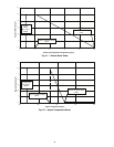
To configure this option with the Touch Pilot™ display:
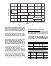
To configure this option with the Navigator™ display:
NOTE: Operation of the head pressure control valve can be
verified by entering Quick Test. From the Navigator display,
go to Service Test\QUIC\FAN.A. From the Touch Pilot dis-
play, go to MAIN MENU\Status\QCK_TST1\Q_VFANA.
PRE-START-UP
Do not attempt to start the chiller until the following checks
have been completed.
System Check
1. Check to ensure the unit is level per the installation
instructions.
2. Electrical power source must agree with unit nameplate.
3. Check that auxiliary components, such as the chilled fluid
and condenser fluid circulating pumps, air-handling
equipment, or any other equipment to which the chiller
supplies liquid are operational. Consult manufacturer's in-
structions. If the unit has field-installed accessories, be
sure all are properly installed and wired correctly. Refer
to unit wiring diagrams.
4. Open compressor suction service valves (if equipped).
5. Open discharge, liquid line, oil line, and economizer (if
equipped) service valves.
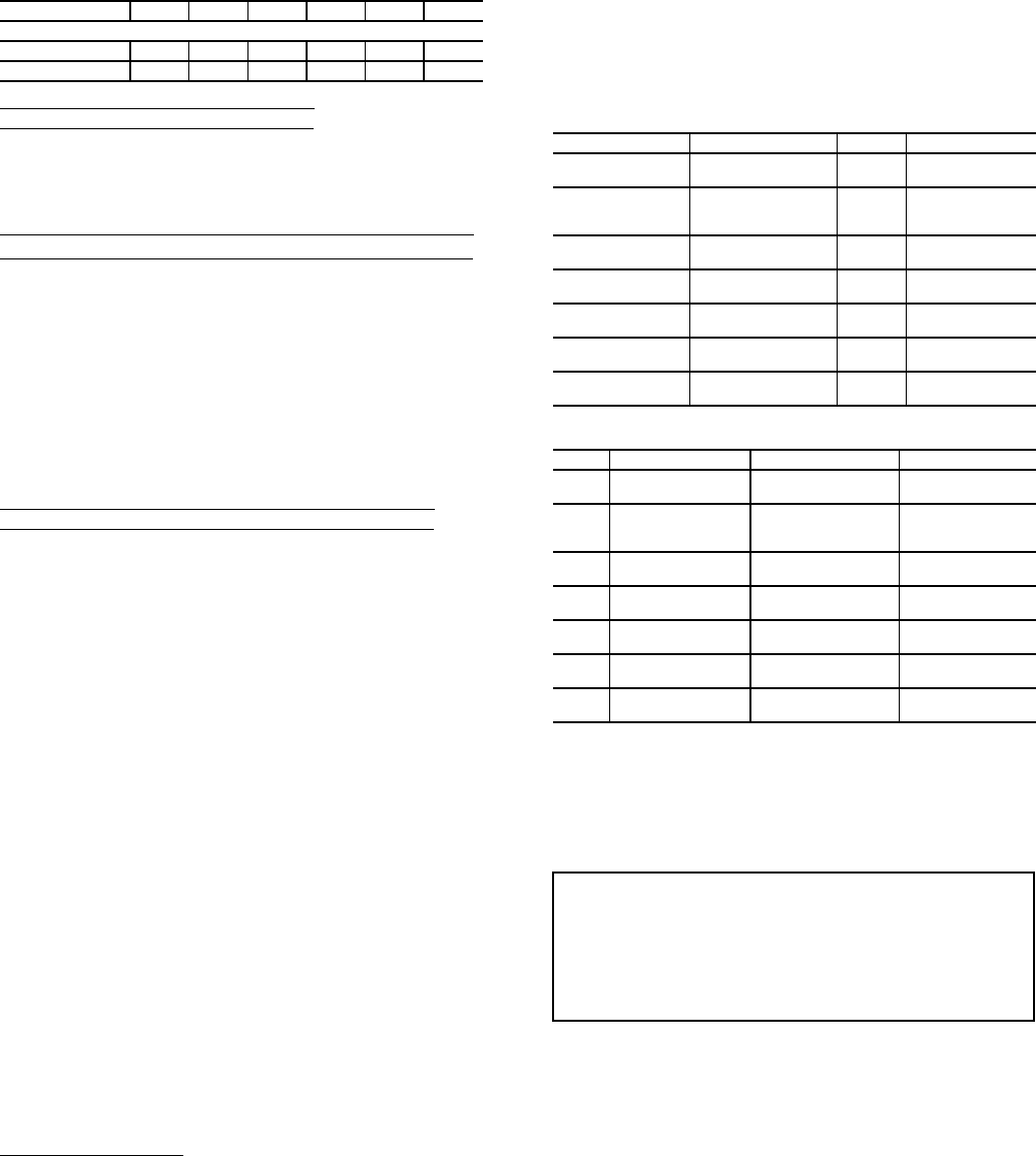
30XW UNIT SIZE 150 175 200 325 350 400
Compressor Nominal Capacity (tons)
Circuit A 182 182 204 182 182 204
Circuit B — — — 182 182 204
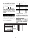
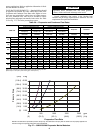
DISPLAY NAME PATH LINE NO. VALUE
Condenser Water
Val Sel
Service FACTORY 13 YES
Water Val
Condensing Stp
Setpoint 38
Range: 80 to120 F
(26.7 to 48.9 C)
Default: 86 F (30 C)
Recl Valve Min
Position
Service SERVICE1 19
Range: 0 to 50%
Default: 20%
Recl Valve Max
Position
Service SERVICE1 20
Range: 20 to 100%
Default: 100%
Prop PID Gain
Varifan
Service SERVICE1 6
Range: -20 to 20
Default: 2.0
Int PID Gain
Varifan
Service SERVICE1 7
Range: -5.0 to 5.0
Default: 0.2
Deri PID Gain
Varifan
Service SERVICE1 8
Range: -20 to 20
Default: 0.4
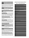
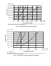
ITEM ITEM EXPANSION PATH VALUE
CON.V
Condenser Valve
Select
Configuration UNIT YES
W.SCT Water Val Cond Stp Setpoint MISC
Range: 80 to140 F
(26.7 to 60 C)
Default: 86 F (30 C)
HR.MI
Reclaim Water Valve
Min
Configuration SERV
Range: 0 to 50%
Default: 20%
HR.MA
Reclaim Water Valve
Max
Configuration SERV
Range: 20 to 100%
Default: 100%
HD.PG
Varifan Proportion
Gain
Configuration SERV
Range: –10 to 10
Default: 2.0
HD.DG
Varifan Derivative
Gain
Configuration SERV
Range: –10 to 10
Default: 0.4
HD.IG Varifan Integral Gain Configuration SERV
Range: –10 to 10
Default: 0.2
IMPORTANT: Complete the Start-Up Checklist
for 30XW Liquid Chillers at the end of this publication.
The checklist assures proper start-up of a unit, and
provides a record of unit condition, application
requirements, system information, and operation at
initial start-up.