


41
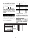
To configure this option with the Navigator display:
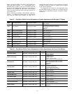
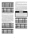
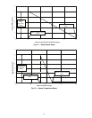
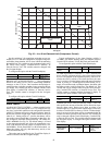
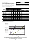
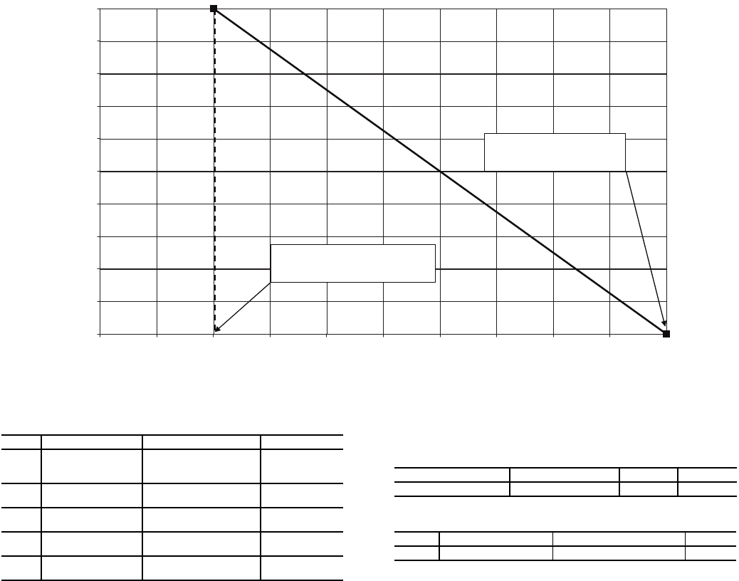
In the following example, a 4 mA signal is Demand Limit
for compressor current is 2000 amps and a 20 mA Demand
Limit signal corresponds with a compressor current of 0 amps.
The 4 to 20 mA signal is connected to TB6-1 and TB6-2. The
demand limit is a linear interpolation between the two values
entered. If the machine receives a 12 mA signal, the machine
controls will limit the total compressor current capacity to
1000 amps. See Fig. 25.
CCN LOADSHED CONTROLLED DEMAND LIMIT —
To configure Demand Limit for CCN Loadshed control, the
unit Operating Type Control must be in CCN control. With the
Touch Pilot™ display, the machine must be started with CCN
Control. For the Navigator™ display, the Operating Control
Type (I/O Button, OPER) must be CCN CONTROL.
The unit must be controlled by a Chillervisor module. The
Chillervisor module can force the demand limit variable and
directly control the capacity of the machine. Additionally, the
unit’s set point will be artificially lowered to force the chiller to
load to the demand limit value.
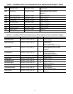
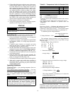
Ice Storage Operation — Chiller operation can be
configured to make and store ice. The energy management
module and an Ice Done Switch are required for operation in
the Ice Mode. In this configuration, the machine can operate
with up to three cooling set points: Cooling Set Point 1 (Cool-
ing Setpoint 1, CSP.1) is used during the Occupied period;
Cooling Set Point 2 (Cooling Setpoint 2, CSP.2) is used dur-
ing the Unoccupied period when the ice build is complete (Ice
Done Switch is closed); and Cooling Ice Set Point (Cooling
Ice Setpoint, CSP.3) is used during the unoccupied period
while ice is building (Ice Done Switch is open).
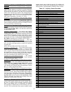
To configure this option with the Touch Pilot display:
To configure this option with the Navigator display:
A power cycle is required for the values to take effect.
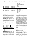
Broadcast Configuration — The 30XW chiller is ca-
pable of broadcasting time, date, and holiday status to all ele-
ments in the CCN system. In the stand-alone mode, broadcast
must be activated to utilize holiday schedules and adjust for
daylight saving time. If the chiller is to be connected to a CCN
system, determine which system element is to be the network
broadcaster to all other system elements. Broadcast is activated
and deactivated in the BRODEFS Table. It is accessible from
Touch Pilot display (Config BRODEFS) or through Network
Service Tool. It is not accessible through Navigator display.
Only one element should be configured as a broadcaster. If
a broadcast is activated by a device that has been designated as
a network broadcaster, then broadcasted time, date, and holiday
status will be updated over the CCN system. If broadcast is en-
abled, a broadcast acknowledger must also be enabled. The ac-
knowledger cannot be the same machine as the broadcasting
machine.
ACTIVATE — The Activate variable enables the broadcast
function of the ComfortLink controls. If this variable is set to 0,
this function is not used and holiday schedules and daylight
savings compensation are not possible. Setting this variable to
1 allows the machine to broadcast and receive broadcasts on
the network. The following information is broadcast: the time
with compensation for daylight savings, date, and holiday flag.
ITEM ITEM EXPANSION PATH VALUE
DMDC
Demand Limit
Select
Configuration RSET
4-20MA INPUT
Default =
NONE
DMMX
mA for 100%
Demand Lim
Configuration RSET
Default =
0.0 mA
DMZE
mA for 0%
Demand Limit
Configuration RSET
Default =
10.0 mA
CUR.S
Current Limit
Select
Configuration OPTN
YES
Default: NO
CUR.F
Current Limit
at 100%
Configuration OPTN
Default =
2000
DISPLAY NAME PATH LINE NO. VALUE
Ice Mode Enable Config USER 42 Yes
ITEM ITEM EXPANSION PATH VALUE
ICE.M Ice Mode Enable Configuration OPTN ENBL
0
10
20
30
40
50
60
70
80
90
100
12 14 16 18
20
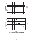
mA Demand Limit Signal
% Demand Limit
mA For 0% Demand Limit,
DMZE
mA For 100% Demand Limit,
DMMX
0
2
46
8 10
Fig. 24 — 4 to 20 mA Demand Limit (Capacity)
a30-4831