


29
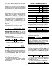
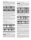
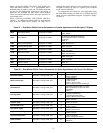
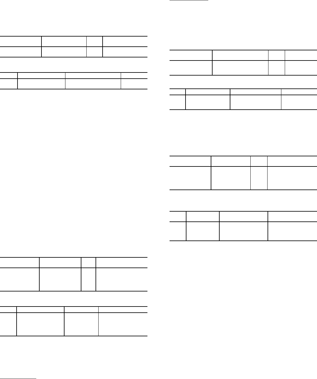
Machine Start Delay — An option to delay the start of
the machine is also available. This parameter is useful in keep-
ing multiple machines from starting at the same time in case of
a power failure. The parameter has a factory default of
1 minute. This parameter also has a role in the timing for a
chilled water flow switch alarm. The flow switch status is not
checked until the delay time has elapsed.
To configure this option with the Touch Pilot display:
To configure this option with the Navigator display:
Circuit/Compressor Staging and Loading —
The AquaForce
®
30XW chillers employ one compressor per
circuit. As a result, circuit and compressor staging are the
same. The control has several control option parameters to load
the compressors. The circuit/compressor start can be config-
ured as well as the loading of each circuit/compressor.
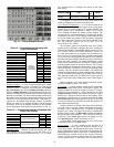
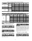
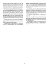
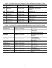
CIRCUIT/COMPRESSOR STAGING — The control can be
configured to decide which circuit/compressor starts first, by
configuring Lead/Lag Circuit Select (Staged Loading
Sequence, LLCS). Three options for this variable are allowed:
Automatic Lead-Lag, Circuit A Leads or Circuit B Leads. The
factory default is Automatic Lead-Lag.
The automatic lead-lag function determines which circuit/
compressor starts. When enabled, the control will determine
which circuit/compressor starts to even the wear of the com-
pressor. The compressor wear factor (combination of starts and
run hours) is used to determine which compressor starts.
Compressor Wear Factor = (Compressor Starts) + 0.1 (Com-
pressor Run Hours)
The circuit/compressor with the lowest compressor wear
factor is the circuit that starts first.
If starting a particular circuit/compressor first is desired, that
can also be configured with the same variable.
To configure this option with the Touch Pilot display:
To configure this option with the Navigator display:
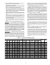
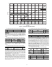
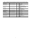
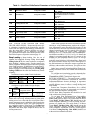
CIRCUIT/COMPRESSOR LOADING — The control can
be configured to stage the circuit/compressors. The Loading
Sequence Select (Circuit Loading Sequence, LOAD) setting
determines how the control will perform loading. The configu-
ration can be set to Equal or Staged.
Equal Loading
— With Equal loading, the circuit which starts
first will maintain the minimum stage of capacity with the slide
valve fully unloaded. When additional capacity is required, the
next circuit with the lowest compressor wear factor is started
with its slide valve at minimum position. As additional capaci-
ty is required, the slide valve for a circuit will be adjusted in
approximately 5% increments to match capacity requirements.
The control will alternate between circuits to maintain the same
percentage of capacity on each circuit.
Staged Loading
— If staged loading is selected, the circuit
which starts first will gradually load its slide valve to match
capacity requirements until the circuit is fully loaded. Once the
circuit is fully loaded and additional capacity is required, the
control will start an additional circuit fully unloaded. The con-
trol will gradually unload the circuit which was fully loaded to
match capacity requirements.
To configure this option with the Touch Pilot™ display:
To configure this option with the Navigator™ display:
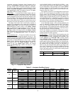
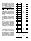
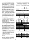
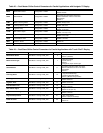
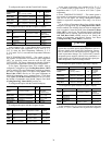
Minimum Load Control — Minimum Load Control
can be a factory-installed option or a field-installed accessory.
If installed, and its operation is desired, the Minimum Load
Control must be enabled. Once enabled, the valve will be oper-
ational only during the first stage of cooling.
To configure this option with the Touch Pilot display:
A power cycle is required for the values to take effect.
To configure this option with the Navigator display:
A power cycle is required for the values to take effect.
Dual Chiller Control — The dual chiller routine is
available for the control of two units installed in series or paral-
lel supplying chilled fluid on a common loop. One chiller must
be configured as the master chiller, the other as the slave chill-
er. An additional leaving fluid temperature thermistor (dual
chiller LWT) must be installed in the common chilled water
piping as described in the Installation Instructions for both the
master and slave chillers. See the Field Wiring section in the
30XW Installation Instructions for dual chiller LWT sensor
control wiring.
The control algorithm relies on several parameters that must
be field configured for operation. Both chillers must be on the
same Carrier Comfort Network
®
bus with different addresses.
On both chillers, Master/Slave Select (Master/Slave Select,
MSSL) must be enabled. The water piping arrangement, Chill-
ers in Series (Chiller in Series, SERI), must be configured.
The master chiller must be programmed with the Slave Chiller
Address (Slave Address, SLVA). Additional optional pro-
gramming parameters may be configured to meet application
requirements.
Lead/Lag Balance Select (Lead Lag Select, LLBL) deter-
mines which chiller is the lead machine. The options are Al-
ways Lead, Lag if Fail, and Runtime Select. Under Runtime
Select control, the lead chiller will change based on the time in-
crement selected in the Lead/Lag Balance Delta configuration
(Lead/Lag Balance Data, LLBD). If the run hour difference
DISPLAY NAME PATH
LINE
NO.
VALUE
Unit Off to
On Delay
Main Menu
Config USER
6 Default = 1 Minute
ITEM ITEM EXPANSION PATH VALUE
DELY Minutes Off Time Configuration OPTN
Default =
1 Minute
DISPLAY NAME PATH
LINE
NO.
VALUE
Circuit Loading
Sequence
Main Menu
Config USER
1
0 (Automatic Lead-lag)
1 (Circuit A Leads)
2 (Circuit B Leads)
Default = 0
(Automatic Lead-lag)
ITEM ITEM EXPANSION PATH VALUE
LLCS
Lead/Lag
Circuit Select
Configuration
OPTN
Range: Automatic,
Cir A Leads,
Cir B Leads,
Cir C Leads
Default – Automatic
DISPLAY NAME PATH
LINE
NO.
VALUE
Staged Loading
Sequence
Main
Menu Config USER
4
Default = No
No (Equal)
Yes (Staged)
ITEM ITEM EXPANSION PATH VALUE
LOAD
Loading Sequence
Select
Configuration OPTN
Default = Equal
Equal
Staged
DISPLAY NAME PATH
LINE
NO.
VALUE
Hot Gas
Bypass Select
Main
Menu Service
FACTORY
14
Default = No
No (No Minimum
Load Control)
Yes (Minimum Load
Control Installed)
ITEM
ITEM
EXPANSION
PATH VALUE
HGBP
Hot Gas
Bypass Select
Configuration UNIT
No = No Minimum
Load Control
Yes = Minimum Load
Control Installed