


25
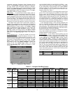
CCN Control
— With CCN Operating Type control, the ma-
chine operates under CCN control as long as the Enable/Off/
Remote Contact Switch is in the Enable or Remote Contact
position (external contacts closed.) To operate under this
Operating Control, OPER must be set to CCN CONTROL. An
external CCN device, such as Chillervisor, controls the On/Off
state of the machine. When controlled by a Chillervisor, it is
recommended that the Auto Start When SM Lost (AU.SM) be
set to Yes.
Careful evaluation of Chilled Water Plant control should be
reviewed. In the event Local Control is established, be sure that
all pumps, valves, and other devices are capable of operating
properly. In the event of a loss of communication with the net-
work, the machine will start and be controlled locally. The
CCN device forces the variable CHIL_S_S to control the chill-
er. The Unit Run Status (STAT) will indicate the current status
of the machine (OFF, RUNNING, STOPPING or DELAY),
depending on the CCN command. The unit Occupied status
(OCC) will indicate the current occupied state according to the
CCN command and will be displayed as either NO or YES.
The Status Unit Control Type (CTRL) will be LOCAL OFF
when the Enable/Off/Remote Contact switch is Off. The Status
Unit Control Type will be CCN when the Enable/Off/Remote
Contact switch input is Closed and the CHIL_S_S variable is
Stop or Start.
For Dual Chiller Control applications, the Slave Chiller
must be enabled using the CCN CONTROL option.
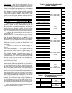
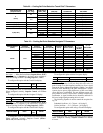
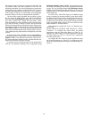
Entering Fluid Control Option — The factory de-
fault for the chilled water fluid set point is controlling to the
leaving water temperature. An option to configure the machine
for entering water control is available. The control operation
remains the same except the control point is focused on the
entering water temperature, rather than the leaving water tem-
perature when configured.
To configure this option for the Touch Pilot™ display:
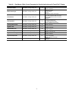
To configure this option for the Navigator™ display:
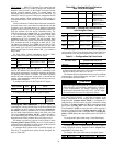
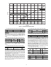
Cooling Set Point Selection — Several options for
controlling the Leaving Chilled Water Set Point are offered and
are configured by the Cooling Set Point Select (Setpoint Se-
lect, SP.SE) variable. In addition to the Cooling Set Point Se-
lect, Ice Mode Enable discussed later in this book, and Heat
Cool Select (Heat/Cool Select, HC.SE) variables also have a
role in determining the set point of the machine. All units are
shipped from the factory with the Heat Cool Select set to 0.
All default set points are based on Leaving Water Control
(Entering Fluid Control, EWTO) set to No. Values must be
confirmed for the individual set points. Limits for the set points
are listed in the configurations noted below.
To configure these options for the Touch Pilot display, see
Table 20A. To configure these options for the Navigator dis-
play, see Table 20B.
Table 20A — Cooling Set Point Selection
with Touch Pilot Display
Table 20B — Cooling Set Point Selection
with Navigator Display
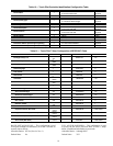
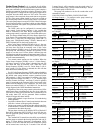
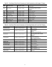
In all cases, there are limits on what values are allowed for
each set point. These values depend on the Cooler Fluid Type
and the Brine Freeze Set point, discussed later. See Table 21.
Table 21 — Configuration Set Point Limits
*The minimum set point for Medium Temperature Brine applications
is related to the Brine Freeze Point. The set point is limited to be no
less than the Brine Freeze Point +5° F (2.8° C).
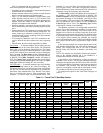
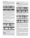
The Setpoint Select configuration can be set to five different
control options: Set Point Occupancy, Set Point 1, Set Point 2,
4-20 mA Input, and Dual Switch.
SET POINT OCCUPANCY — Set Point Occupancy is the
default configuration for the Setpoint Select variable. When
Setpoint Select (Setpoint Select, SP.SE) is configured to 0
(Setpoint Occ), the unit’s active set point is based on Cooling
Set Point 1 (Cooling Setpoint 1, CSP.1) during the occupied
period while operating under Time Schedule 1 (SCH1). If the
Time Schedule 2 (SCH2) is in use, the unit’s active set point is
based on Cooling Set Point 1 (Cooling Setpoint 1, CSP.1) dur-
ing the occupied period and Cooling Set Point 2 (Cooling Set-
point 2, CSP.2) during the unoccupied period. See Tables 22
and 23.
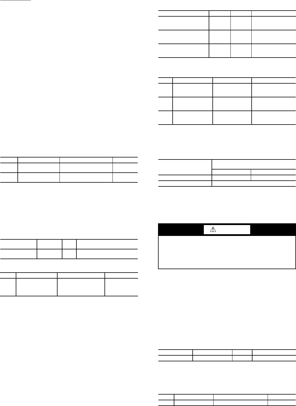
To configure this option while using a Touch Pilot display:
To change this value, a Control Point Force must be applied.
When configured correctly, Setpoint Control (Setpoint Con-
trol, SP.SE) will indicate Auto.
To configure this option while using a Navigator display:
ITEM ITEM EXPANSION PATH VALUE
OPER
Operating Control
Type
Operating
Modes SLCT OPER
CCN
CONTROL
AU.SM
Auto Start when
SM Lost
Configuration SERV YES
DISPLAY NAME PATH
LINE
NO.
VALUE
Entering Fluid
Control
Service\
SERVICE1
5
No = Leaving Water Control
Yes = Entering Water Control
ITEM ITEM EXPANSION PATH VALUE
EWTO Entering Water
Control
Configuration SERV No = Leaving
Water Control
Yes = Entering
Water Control
DISPLAY NAME PATH LINE NO. VALUE
Cooling Setpoint 1 Setpoint 2 Range: 14 to 70 F
(–10.0 to 21.1 C)
Default: 44 F (6.6 C)
Cooling Setpoint 2 Setpoint 3 Range: 14 to 70 F
(–10.0 to 21.1 C)
Default: 44 F (6.6 C)
Cooling Ice Setpoint Setpoint 4 Range: -20 to 32 F
(–28.9 to 0 C)
Default: 44 F (6.6 C)
ITEM ITEM EXPANSION PATH VALUE
CSP.1 Cooling Setpoint 1 Setpoints COOL
Range: 14 to 70 F
(–10.0 to 21.1 C)
Default: 44 F (6.6 C)
CSP.2 Cooling Setpoint 2 Setpoints COOL
Range: 14 to 70 F
(–10.0 to 21.1 C)
Default: 44 F (6.6 C)
CSP.3 Ice Setpoint Setpoints COOL
Range: -20 to 32 F
(–28.9 to 0 C)
Default: 44 F (6.6 C)
SET POINT LIMITS
COOLER FLUID TYPE
(COOLER FLUID TYPE, FLUD)
1, Water 2, Brine
Minimum * 38 F (3.3 C) 14 F (–10.0 C)
Maximum 60 F (15.5 C)
CAUTION
Brine duty application (below 40 F [4.4 C] LCWT) for
chiller normally requires factory modification. Contact a
Carrier Representative for details regarding specific
applications. Operation below 40 F (4.4 C) LCWT with-
out modification can result in compressor failure.
DISPLAY NAME PATH LINE NO. VALUE
Setpoint select Status GENUNIT 25 0 (Setpoint Occupied)
ITEM ITEM EXPANSION PATH VALUE
SP.SE Setpoint Select Operating Modes SLCT Setpoint Occ