


47
6. Fill the chiller fluid circuit with clean water (with recom-
mended inhibitor added) or other non-corrosive fluid to
be cooled. Bleed all air out of high points of system. If
unit is exposed to temperatures below 32 F (0° C), suffi-
cient inhibited propylene glycol or other suitable corro-
sion inhibited antifreeze should be added to the chiller
water and condenser water circuit to prevent possible
freeze-up. The chilled water loop must be cleaned before
the unit is connected. To set the maintenance time for
cleaning and inspecting loop strainers, go to Water Filter
Ctrl (days), W.FIL. Values for this item are counted as
days. Refer to the system pump package literature for
specific internal inspection/cleaning requirements.
7. Check tightness of all electrical connections.
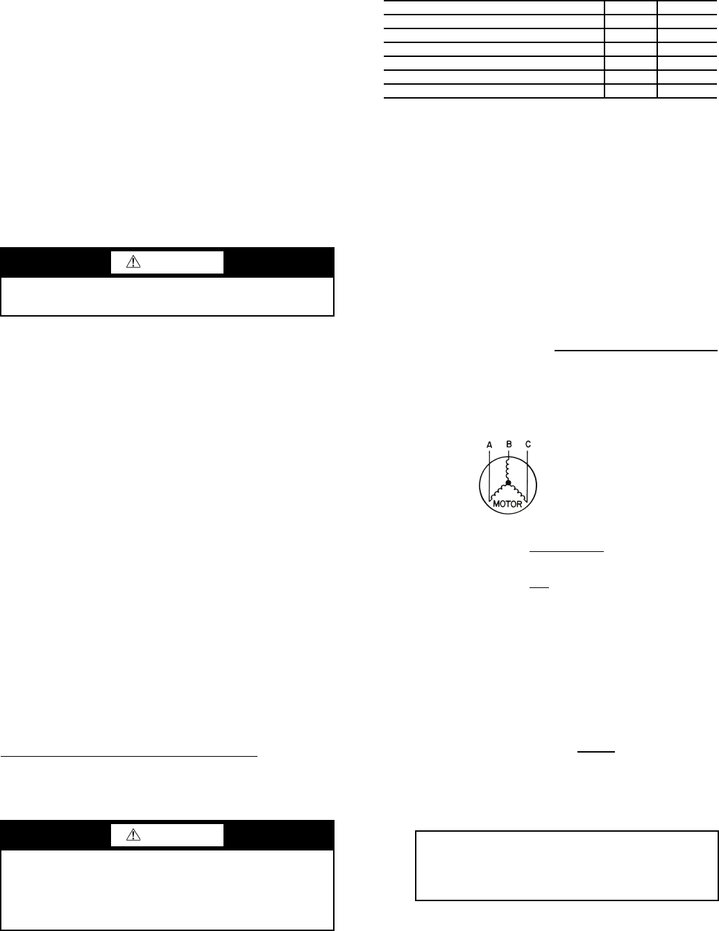
8. Verify power supply phase sequence. The phase sequence
should be A-B-C for proper compressor rotation.
START-UP
Actual Start-Up —
Actual start-up should be done only
under supervision of a qualified refrigeration technician.
1. Be sure all discharge, oil, and suction valves (if equipped)
and liquid line service valves are open.
2. Using the unit control, set leaving-fluid set point (Cool-
ing Setpoint 1, CSP.1). No cooling range adjustment is
necessary.
3. If optional control functions or accessories are being
used, the unit must be properly configured. Refer to
Configuration Options section for details.
4. Start the chilled fluid and condenser pumps, if unit is not
configured for pump control. (Cooler Pumps Sequence,
PUMP=0; Condenser Pump Sequence, HPUM = No)
5. Complete the Start-Up Checklist to verify all components
are operating properly.
6. Check the cooler flow switch for proper operation. En-
sure that the flow switch input indicates closed when the
pump is on and open when the pump is off.
7. Turn Enable/Off/Remote contact switch to Enable position.
8. Allow unit to operate and confirm that everything is
functioning properly. Check to see that leaving fluid
temperature agrees with leaving set point Control Point
(Control Point, CTPT).
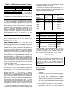
Operating Limitations
TEMPERATURES — Unit operating temperature limits are
listed in Table 35.
Low Condenser Water Temperature Operation
— For con-
denser entering water temperatures between 33 F (0.6 C) and
65 F (18.3 F), field installed accessory head pressure control
valve is required. Contact your Carrier representative for
details.
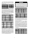
Table 35 — Temperature Limits for Standard Units
LEGEND
*Temperature limit for high condensing/heat reclaim option units are
140 F (60 C).
†For sustained operation, EWT should not exceed 85 F (29.4 C).
**Unit requires brine modification for operation below this
temperature.
VOLTAGE
Main Power Supply — Minimum and maximum acceptable
supply voltages are listed in the Installation Instructions.
Unbalanced 3-Phase Supply Voltage — Never operate a motor
where a phase imbalance between phases is greater than 2%.
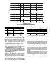
To determine percent voltage imbalance:
The maximum voltage deviation is the largest difference
between a voltage measurement across 2 legs and the average
across all 3 legs.
Example: Supply voltage is 240-3-60.
AB = 243v
BC = 236v
AC = 238v
1. Determine average voltage:
2. Determine maximum deviation from average voltage:
(AB) 243 – 239 = 4 v
(BC) 239 – 236 = 3 v
(AC) 239 – 238 = 1 v
Maximum deviation is 4 v.
3. Determine percent voltage imbalance:
= 1.7%
This voltage imbalance is satisfactory as it is below the
maximum allowable of 2%.
MINIMUM FLUID LOOP VOLUME — To obtain proper
temperature control, loop fluid volume must be at least 3 gal-
lons per ton (3.25 L per kW) of chiller nominal capacity for air
conditioning and at least 6 gallons per ton (6.5 L per kW) for
CAUTION
Do not manually operate contactors. Serious damage to the
machine may result.
CAUTION
Brine duty application (below 40 F [4.4 C] LCWT) for
chiller normally requires factory modification. Contact a
Carrier Representative for details regarding specific
applications. Operation below 40 F (4.4 C) LCWT with-
out modification can result in compressor failure.
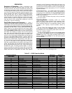
TEMPERATURE F C
Maximum Condenser EWT 110 43.3
Minimum Condenser EWT 65 18.3
Maximum Condenser LWT* 118 47.8
Maximum Cooler EWT† 70 21.1
Maximum Cooler LWT 60 15.6
Minimum Cooler LWT** 40 4.4
EWT — Entering Fluid (Water) Temperature
LWT — Leaving Fluid (Water) Temperature
% Voltage Imbalance = 100 x
max voltage deviation from
avg voltage
average voltage
Average voltage =
243+236+238
3
=
717
3
= 239
% Voltage Imbalance = 100 x
4
239
IMPORTANT: If the supply voltage phase imbal-
ance is more than 2%, contact the local electric
utility company immediately. Do not operate unit
until imbalance condition is corrected.