3
GENERAL
This publication contains controls, operation, start-up, ser-
vice and troubleshooting information for the 30XW150-400
water-cooled liquid chillers with electronic controls. The
30XW chillers are equipped with ComfortLink™ controls and
electronic expansion valves. The AquaForce
®
30XW chillers
offer two different user interface devices, the Touch Pilot™
display and the Navigator ™ display.
Conventions Used in This Manual — The follow-
ing conventions for discussing configuration points for the
Navigator module and Touch Pilot display will be used in this
manual.
Point names for the Touch Pilot display will be shown in
bold. See Appendix A for a complete list of point names. Item
names for the Navigator module will be shown in bold italics.
See Appendix B for the complete path name preceding the item
name. The point and item names in Appendices A and B will
be listed in alphabetical order and the path name for each will
be written with the mode name first, then any sub-modes, each
separated by an arrow symbol ( .
This path name will show the user how to navigate through the
Navigator module or the Touch Pilot display to reach the desired
configuration. The user would scroll through the modes and sub-
modes using the and keys on the Navigator display. For
the Touch Pilot display, the user would simply touch the menu
item on the screen. The arrow symbol in the path name represents
pressing to move into the next level of the menu struc-
ture for the Navigator module, or touching the menu item on the
screen for the Touch Pilot display.
When a value is included as part of the point name, it will be
shown after the point name after an equals sign. If the value
represents a configuration setting, an explanation will be
shown in parentheses after the value. The Touch Pilot name
will be shown first with the Navigator name following. As an
example,
(Staged Loading Sequence = 1, LLCS = Circuit A leads).
Press the and keys simultaneously on
the Navigator module to display an expanded text description of
the point name or value. The expanded description is shown in the
Navigator display tables (Appendix B) but will not be shown with
the path names in text. The Touch Pilot display will show an ex-
panded description of the point name. To view the expanded point
name for the Touch Pilot display go to Appendix A.
The Touch Pilot display configures the unit via the CCN
(Carrier Comfort Network
®
) Tables, which are located in Ap-
pendix C of this manual.
Display Module Usage
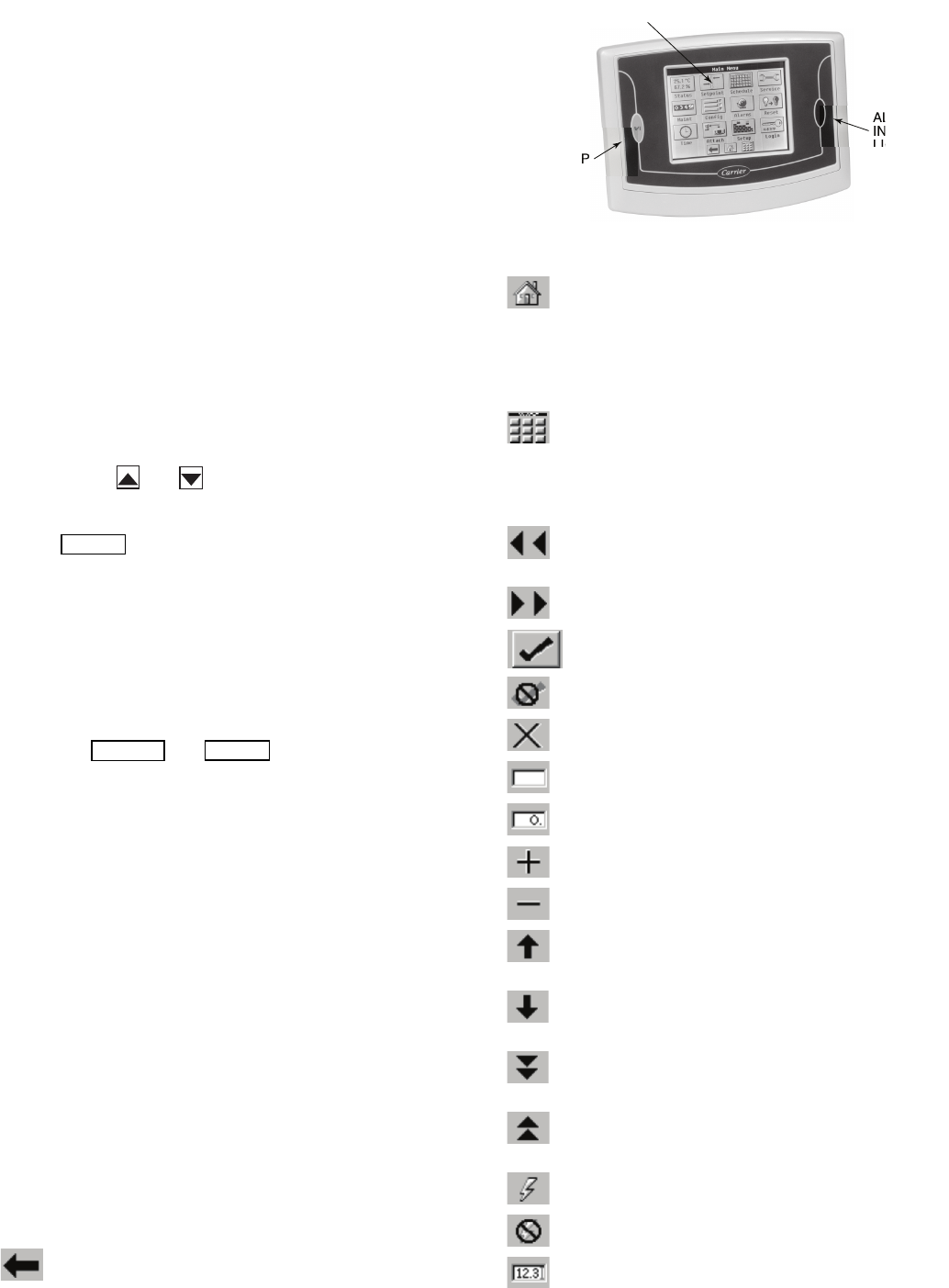
TOUCH PILOT DISPLAY — The Touch Pilot display is the
standard user interface for the AquaForce 30XW chillers with
the ComfortLink control system. The display includes a large
LCD (liquid crystal display) touch screen for display and user
configuration, a Start/Stop button, and an Alarm Indicator LED
(light-emitting diode). See Fig. 1.
The Touch Pilot display can be used to access various
Carrier Comfort Network
®
devices. For operation under these
circumstances, contact your Carrier representative.
Operation of the Touch Pilot display is driven from the
displays on the touch screen. The Touch Pilot display uses the
following screen “buttons” to allow the user to operate the dis-
play and navigate within and between screens.
“BACK” returns to the next higher screen in the
hierarchy.
“HOME” displays the Default Group Display screen
for Touch Pilot display. The Default Screen is a user-
configured display of up to 9 points on each of 8 screens. This
allows for quick access to various, frequently viewed points,
without navigating through the Main Menu structure. This but-
ton is available at all menu levels and returns the user to the
first Default Group Display screen.
“MAIN MENU” displays the Main Menu screen. This
allows access for viewing and configuration, where
possible, of all points supported by the controller. This includes
points such as set point and operational configuration. This
button is available at all menu levels and returns the user to the
Main Menu screen.
“PREVIOUS” moves the user to the next earlier
screen in a group of sequential screens of the same
type.
“NEXT” advances the user to the next screen in a
group of sequential screens of the same type.
“OK” agrees with, or says “yes” to a prompt and per-
forms the appropriate processing.
“NO” rejects, or says “no” to a prompt and performs
the appropriate processing.
“CANCEL” terminates an ongoing action and returns
to the current screen without any other processing.
“CLEAR DATA” clears the data value in a data entry
dialog box. This button is used to clear incorrect data.
“RESET DATA” zeros the data value in a data entry
dialog box.
“ADD” adds the active point to a Group Display
screen.
“REMOVE” deletes a point from a Group Display
screen.
“INCREASE” modifies the value of a field within its
defined limits or “SCROLL UP” and shifts the screen
view up by one item.
“DECREASE” modifies the value of a field within its
defined limits or “SCROLL DOWN” and shifts the
screen view down by one item.
“PAGE DOWN” will replace the items currently on
the screen with the next group of items if the current
table or list has more data than will fit on the screen.
“PAGE UP” will replace the items currently on the
screen with the previous group of items if the current
table or list has more data than will fit on the screen.
“FORCE” begins the process of forcing or overriding
the value of a point.
“AUTO” begins the process of removing a force from
a point.
“MODIFY” begins the process of modifying a config-
uration value.
ALARM
INDICATOR
LIGHT
START-STOP
BUTTON
LCD TOUCH
SCREEN
Fig. 1 — Touch Pilot™ Display
a30-4456 (b&w)


