


11
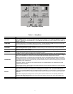
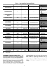
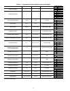
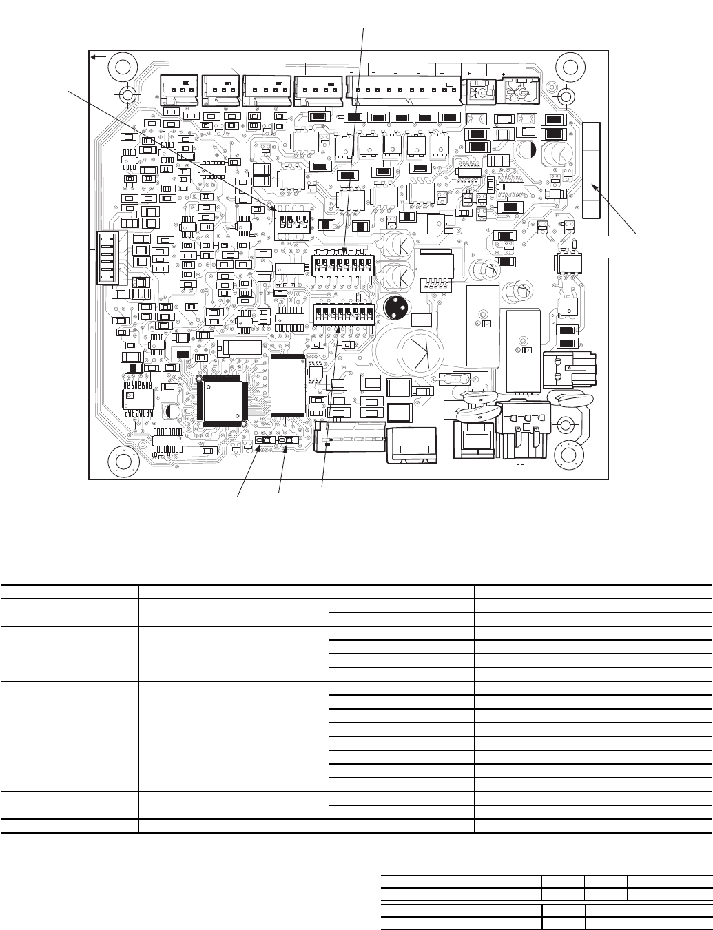
Table 4 — DIP Switch 1 (S1) Inputs
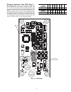
The CPM board DIP switch S2 setting determines the must
trip amps (MTA) setting. See Appendix D for DIP switch set-
tings. The MTA setting which is calculated using the settings
S2 must match the MTA setting in the software or an MTA
alarm will be generated.
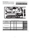
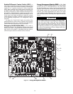
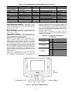
See below for CPM board DIP switch S3 address informa-
tion. See Table 5 for CPM inputs and outputs.
DIP SWITCH POSITION FUNCTION SETTING MEANING
1
Starter Configuration OFF Across-the-line Start
ON Wye-Delta Start
2, 3
Current Transformer (CT) Position OFF (2), OFF (3) CT is located in the main line
ON (2), OFF (3) CT is located in the Delta of the motor
OFF (2), ON (3) Reserved for future use
ON (2), ON (3) Invalid; will cause MTA configuration alarm
4, 5, 6
Current Transformer (CT) Selection OFF (4), OFF (5), OFF (6) 100A/1V CT1
ON (4), OFF (5), OFF (6) 100A/0.503V CT2
OFF (4), ON (5), OFF (6) 100A/0.16V CT3
ON (4), ON (5), OFF (6) Invalid; will cause MTA configuration alarm
OFF (4), OFF (5), ON (6) Invalid; will cause MTA configuration alarm
ON (4), OFF (5), ON (6) Invalid; will cause MTA configuration alarm
OFF (4), ON (5), ON (6) Invalid; will cause MTA configuration alarm
ON (4), ON (5), ON (6) Invalid; will cause MTA configuration alarm
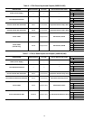
7
Contactor Failure Action OFF All units should be off
ON Used when Shunt Trip is available in the unit
8 Not Used — —
CPM-A DIP Switch 3 1 2 3 4
Address: OFF OFF OFF OFF
CPM-B DIP Switch 3 1 2 3 4
Address: OFF OFF ON OFF
123 45678
0N
40
K
123 45678
0N
40
K
123 4
0N
102
151
102
102
101
101
101
101
100 K
620
561
2x
151
151
151 151 151
151
151
151
151
561
561
2
2x
2
CH
05
CH
06
C
C
CH
10
CH
11
CH
12
CH
13
CH
14
J2
J11
11
12
J9
J10A
J10B
24 VDC/OLL
HPS
1
LOADERS OLS MOTOR COOLING
OIL
PRESS
CH01
CH02
CH03
CH04
SMT
MOT
TMP
DG
TMP
R
R
R
R
S
5
S
5
AUX
102
102
100 K
CH
08
CH
07
01
02
J3
J5
J12
J1
151
151
R20
102
– G +
3 2 1
– G +
3 2 1
100K
101
PRESS
ECO
SI0 STAT US
CT1
CT2
CT3
J8
151
151
151
151
151
561
151
151
151
151
151
151
J4
CH
09
(LEN)
MTA
DIP
SWITCH 3
(S3)
S1
S2
S3
DIP
SWITCH 2
(S2)
DIP
SWITCH 1
(S1)
LOCATION OF
SERIAL NUMBER
STAT US
SIO
(LEN)
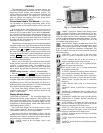
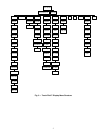
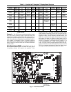
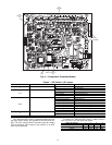
Fig. 9 — Compressor Protection Module
a30-4215