


68
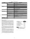
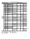
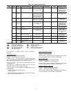
Table 48 — Troubleshooting
LEGEND
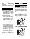
Alarms and Alerts — The integral control system con-
stantly monitors the unit and generates warnings when abnor-
mal or fault conditions occur. Alarms may cause either a circuit
(Alert) or the whole machine (Alarm) to shut down. Alarms
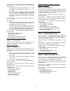
and Alerts are assigned codes as described in Fig. 52. The
alarm/alert indicator LED on the Navigator™ module is
illuminated when any alarm or alert condition is present. If an
Alert is active, the Alarm Indicator LED will blink. If an Alarm
is active, the Alarm Indicator LED will remain on. Currently
active Alerts and Alarms can be found in (Current Alarm,
ALRM).
The controller generates two types of alarms. Automatic
reset alarms will reset without any intervention if the condition
that caused the alarm corrects itself. Manual reset alarms
require the service technician to check for the alarm cause and
reset the alarm. The following method must be followed to
reset manual alarms:
Before resetting any alarm, first determine the cause of the
alarm and correct it. To reset the alarm, set R.ALM to YES.
The alarms will be reset. Indicator light will be turned off when
switched correctly. Do not reset the chiller at random without
first investigating and correcting the cause(s) of the failure.
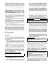
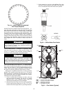
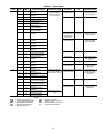
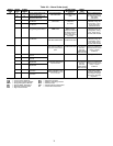
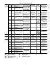
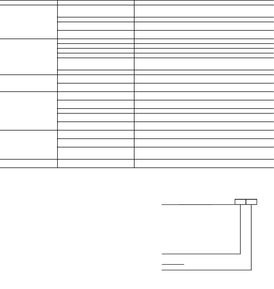
Each alarm is described by a three or four-digit code. The
first one or two digits indicate the alarm source and are listed in
Fig. 52. The last two digits pinpoint the problem. See Table 49.
SYMPTOM POSSIBLE CAUSE POSSIBLE REMEDY
Unit Does Not Run Check for power to unit • Check overcurrent protection device.
• Check non-fused disconnect (if equipped).
• Restore power to unit.
Wrong or incorrect unit configuration Check unit configuration.
Active alarm Check Alarm status. See the Alarms and Alerts section and follow
troubleshooting instructions.
Active operating mode Check for Operating Modes. See the Operating Modes section and follow trouble-
shooting instructions
Unit Operates too Long or
Continuously
Low refrigerant charge Check for leak and add refrigerant.
Compressor or control contacts welded Replace contactor or relay.
Air in chilled water loop Purge water loop.
Non-condensables in refrigerant circuit. Remove refrigerant and recharge.
Inoperative EXV • Check EXV, clean or replace.
• Check EXV cable, replace if necessary.
• Check EXV board for output signal.
Load too high Unit may be undersized for application
Circuit Does Not Run Active alarm Check Alarm status. See the Alarms and Alerts section and follow
troubleshooting instructions.
Active operating mode Check for Operating Modes. See the Operating Modes section and follow trouble-
shooting instructions.
Circuit Does Not Load Active alarm Check Alarm status. See the Alarms and Alerts section and follow
troubleshooting instructions.
Active operating mode Check for Operating Modes. See the Operating Modes section and follow trouble-
shooting instructions.
Low saturated suction temperature See Operating Modes 21 and 22.
High circuit suction superheat The circuit capacity is not allowed increase if circuit superheat is greater than 36 F
(20 C). See Alarms 74 and 75 for potential causes.
Low suction superheat The circuit capacity is not allowed to increase if the circuit superheat is less than
18° F (10° C). See Alarms 74 and 75 for potential causes.
Compressor Does Not Run Active alarm Check Alarm status. See the Alarms and Alerts section and follow
troubleshooting instructions.
Active operating mode Check for Operating Modes. See the Operating Modes section and follow trouble-
shooting instructions.
Inoperative compressor contactor • Check control wiring.
• Check scroll protection module.
• Check contactor operation, replace if necessary.
Chilled Water Pump is ON, but
the Machine is OFF
Cooler freeze protection Chilled water loop temperature too low. Check cooler heater.
EXV — Electronic Expansion Valve
Alarm Suffix
Code Number to identify source
Alarm Descriptor
th
.01
Alarm Prefix
A1 – Compressor A1 Failure
B1 – Compressor B1 Failure
Co – Communication Failure
FC – Factory Configuration Error
MC – Master Chiller Configuration Error
P – Process Failure
Pr – Pressure Transducer Failure
Sr – Service Notification
th – Thermistor Failure
Alarm
Fig. 52 — Alarm Description
A30-4847