


44
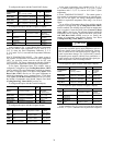
Override #2: Circuit A Low Saturated Suction Temperature
in Cooling
Override #3: Circuit B Low Saturated Suction Temperature
in Cooling
These overrides attempt to avoid the low suction temperature
alarms and are active only when the compressor is running
beyond the fully unloaded level. The slide valve in the affected
circuit will be decreased in position if the Saturated Suction
Temperature is less than Brine Freeze Set Point (Brine Freeze
Setpoint, LOSP) –18.0 F (–10 C) for 90 seconds, or the Satu-
rated Suction Temperature is less than –4 F (–20 C).
Override #5: Low Temperature Cooling and High Tempera-
ture Heating — This override decreases capacity when the dif-
ference between the Control Point (Control Point, CTPT) and
the Leaving Water Temperature (Cooler Leaving Fluid, LWT)
reaches a predetermined limit and the rate of change of the wa-
ter is 0º F per minute or still decreasing.
Override #6: Low Temperature Cooling and High Temperature
Heating — This override decreases capacity (approximately
5% of circuit capacity) when the Entering Water Temperature
(Cooler Entering Fluid, EWT) is less than the Control Point
(Control Point, CTPT).
Override #7: Ramp Loading
— No capacity stage increase
will be made if the unit is configured for ramp loading (Ramp
Loading Select, RL.S=ENBL) and the difference between the
Leaving Water Temperature and the Control Point is greater
than 4º F (2.2º C) and the rate of change of the leaving water is
greater than Cool Ramp Loading Rate (Cooling Ramp Load-
ing, CRMP). Operating mode 5 (MD05) will be in effect.
Override #8: Service Manual Test Override
— This over-
ride mode indicates the unit has been placed into Service Test
mode. The user can then use Service Test functions to test the
unit. All safeties and higher priority overrides are monitored
and acted upon.
NOTE: The user cannot activate this override mode.
Override # 9: Demand Limit
— This override mode is active
when a command to limit the capacity is received. If the
current unit capacity is greater than the active capacity limit
value, a stage is removed. If the current capacity is lower than
the capacity limit value, the control will not add a stage that
will result in the new capacity being greater then the capacity
limit value. Operating mode 4 (MD04) will be in effect.
Override #10: Cooler Interlock Override
— This override
prohibits compressor operation until the Cooler Interlock
(Cooler Flow Switch, LOCK) is closed.
Override #11: High Temperature Cooling and Low Temper-
ature Heating — This override algorithm runs once when the
unit is switched to ON. If the difference between the Leaving
Water Temperature (Cooler Leaving Fluid, LWT) and the
Control Point (Control Point, CTPT) exceeds a calculated
value and the rate of change of the water temperature is greater
than –0.1º F/min, a stage will be added.
Override #12: High Temperature Cooling and Low Temper-
ature Heating — This override runs only when Minimum
Load Control is Enabled, (Hot Gas Bypass Select, HGBP)
and is set to 1, 2 or 3. This override will add a stage of capacity
if the next stage is Minimum Load Control, when the differ-
ence between the Leaving Water Temperature (Cooler Leav-
ing Fluid, LWT) and the Control Point (Control Point, CTPT)
exceeds a calculated value and the rate of change of the water
temperature is greater than a fixed value.
Override #13: Minimum On/Off and Off/On Time Delay
—
Whenever a capacity change has been made, the control will
remain at this capacity stage for the next 90 seconds. During
this time, no capacity control algorithm calculations will be
made. If the capacity step is a compressor, an additional
90-second delay is added to the previous hold time (see Over-
ride #22). This override allows the system to stabilize before
another capacity stage is added or removed. If a condition of a
higher priority override occurs, the higher priority override will
take precedence. Operating Mode 10 (MD10) will be in effect.
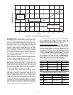
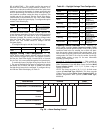
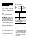
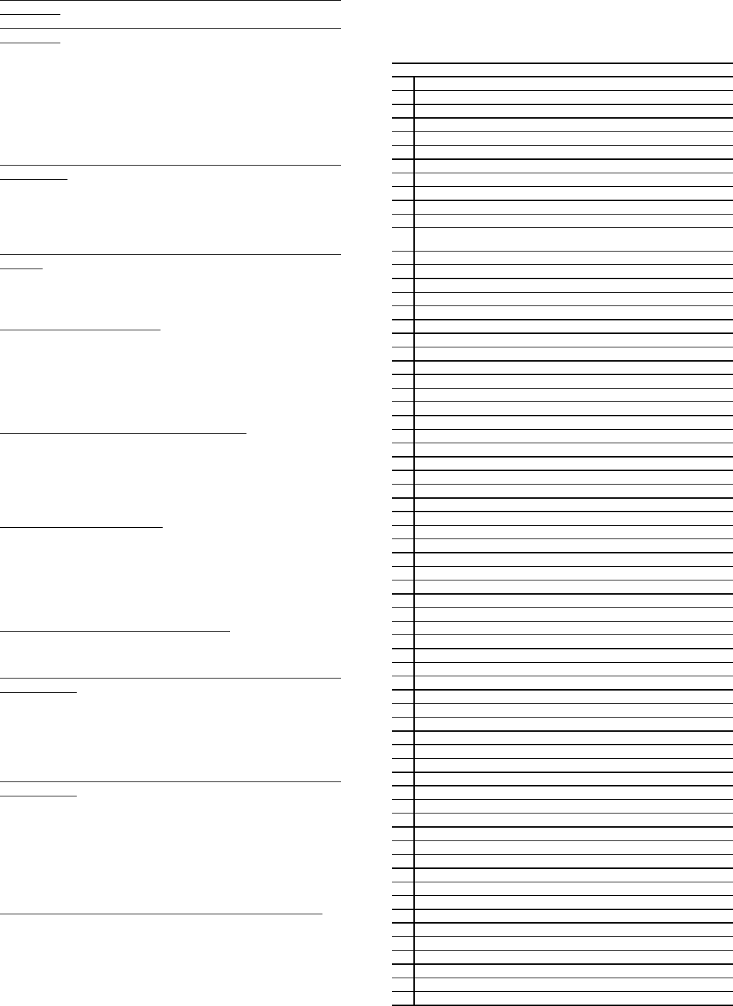
Table 33 — Capacity Control Overrides
CAPACITY CONTROL OVERRIDES
1 Cooler Freeze Protection
2 Circuit A Low Saturated Suction Temperature in Cooling
3 Circuit B Low Saturated Suction Temperature in Cooling
4 —
5 Low Temperature cooling and High Temperature Heating (LWT)
6 Low Temperature cooling and High Temperature Heating (EWT)
7 Ramp Loading
8 Service Manual Test Override
9 Demand Limit
10 Cooler Interlock Override
11 High Temperature Cooling and Low Temperature Heating
12 High Temperature Cooling and Low Temperature Heating
(minimum load control in effect)
13 Minimum On/Off and Off/On Time Delay
14 Slow Change Override
15 System Manager Capacity Control
16 Circuit A High Pressure Override
17 Circuit B High Pressure Override
18 —
19 Standby Mode
20 —
21 —
22 Minimum On Time Delay
23 Circuit A Low Saturated Suction Temperature in Cooling
24 Circuit B Low Saturated Suction Temperature in Cooling
25 —
26 —
27 —
28 —
29 —
30 —
31 —
32 —
33 —
34 Circuit A Low Refrigerant Charge
35 Circuit B Low Refrigerant Charge
36 —
37 —
38 —
39 —
40 —
41 Circuit A High Current Override
42 Circuit B High Current Override
43 —
44 Circuit A High Suction Superheat at Part Load
45 Circuit B High Suction Superheat at Part Load
46 —
47 —
48 —
49 —
50
—
51 —
52 —
53 Circuit A Delay for Unloading the Slide Valve
54 Circuit B Delay for Unloading the Slide Valve
55 —
56 —
57 —
58 —
59 Circuit A Low Oil Level
60 Circuit B Low Oil Level
61 —
62 Circuit A High Motor Temperature Override
63 Circuit B High Motor Temperature Override
64 —
65 —
66 Circuit A High Discharge Gas Override
67 Circuit B High Discharge Gas Override