


4
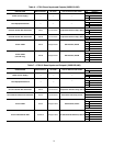
“ALARM INDICATOR LIGHT” activates when a
new alarm condition occurs. The alarm indicator light
LED, located on the right side of the display, remains
activated until it is manually reset using the Reset button on the
Main menu.
“START/STOP BUTTON” enables the user to start
or stop the chiller from the Touch Pilot™ display.
See Enable-Off-Remote Contact Switch (SW1) on
page 16 for additional information.
Several items are password protected. When required, a
Password dialog box will be displayed for field input of the
password. The default password is 3333. The password can be
changed if desired.
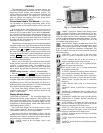
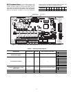
Power-Up Display
— When the Touch Pilot display is pow-
ered up, it displays an initialization progress bar and attaches
(initiates communication) to the Main Base Board. The Touch
Pilot display then shows that controller’s default Group Dis-
play screen. See Fig. 2. This is a user-configured display screen
with up to 9 points on 8 separate screens. For more information
on adding or removing points from the Group Display screen,
see the Group Display Screens section on page 7.
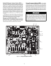
Touch any of the screen point buttons and Point Data Dialog
box will be displayed with expanded information. In the exam-
ple shown, the CTRL_PNT button in the bottom left corner
was selected. See Fig. 2 and 3.
To exit the box, press .
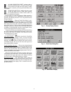
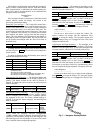
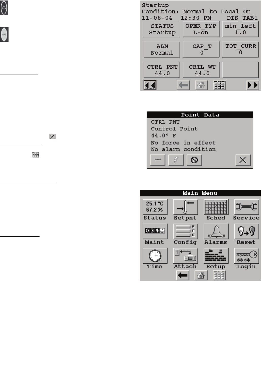
Main Menu Display
— The default screen for the Touch Pilot
controller is the Group Display screen. To access the Main
Menu, press the button. The screen shown in Fig. 4 will be
displayed. Selecting a button will display the screens associat-
ed with that category. The user can also access the login screen
from the Main Menu if needed.
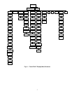
Touch Pilot Menu Structure
— The user can navigate through
the Touch Pilot display screens by selecting the buttons that ap-
pear on the screen. When a button is selected, either a sub-
menu or a list of point names and values will be shown. Sub-
menus will display a list of associated point names. See Fig. 5
for the Touch Pilot menu structure.
If the list of point names and values are shown, the top line
of the display is the table name. The line and total line counter
is displayed in the upper right corner of the display. Selecting
an item will cause a Point Data dialog box to appear.
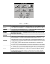
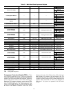
Setup Menu Screen
— The Setup Menu screen, shown in
Fig. 6, is accessed by pressing the Setup button from the Main
Menu. This configuration allows the user to configure the basic
operation and look of the display. Table 1 summarizes the Set-
up Menu functions.
Fig. 2 — Group Display Screen
Fig. 3 — Point Data Dialog Box
Fig. 4 — Main Menu Display
a30-4910.ep
a30-4471
a30-4472
PDS-XAXQXWPDS-XAXQXW