


130
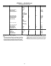
APPENDIX C — CCN TABLES (cont)
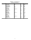
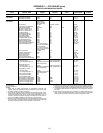
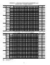
SERVICE CONFIGURATION TABLES
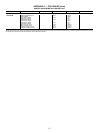
*Not supported.
†0 = No economizer.
NOTES:
1. Table used to disable compressors for maintenance purposes. The
capacity control will consider that these compressors (once set to YES)
are failed manually (no alarm will appear).
2. Enter unit size. This item allows the controls to determine capacity of each
compressor and the total number of fans on each circuit based on a com-
pressor arrangement array (can be viewed in table FACTORY2). It is not
necessary to enter compressor capacity and number of fans on each cir-
cuit. See the 30XW Installation Instructions for more information.
3. Number of fans controlled directly by a variable speed fan actuator using
0 to 10 vdc signal. This will enable the controls to determine the remaining
discrete fan staging outputs from the total fans on each circuit.
4. Used for extra functions with the purpose of energy management such as
occupancy override switch, ice storage, setpoint reset, and demand limit.
5. Compressor capacity will be automatically determined if unit size entered
in FACTORY table matches the values in the unit compressor configura-
tion table.
6. Total number of fans includes fans controlled by a variable speed fan. This
value will be automatically populated if unit size entered in FACTORY
table matches the values in the unit compressor configuration table.
TABLE DISPLAY NAME RANGE DEFAULT UNITS POINT NAME
WRITE
STATUS
TABLE USED FOR DISABLE COMPRESSORS (see notes)
CP_UNABL
(See Notes)
Compressor A Disable No/Yes No un_cp_a
Compressor B Disable No/Yes No un_cp_b
Compressor C Disable No/Yes No un_cp_c
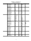
FACTORY
(See Notes)
Unit Type 1 (Cooling Only)
2 (Heat Pump)*
3 (Water Cooled)
4 (Heat Machine)
1 unit_typ
Unit Capacity 0 to 1800 Nominal Unit Size unitsize
Power Frequence 60HZ Sel Yes/No Yes freq_60H
Power Supply Voltage 200 to 660 460 volts voltage
NB Fans on Varifan Cir A 0 to 6 1 varfan_a
NB Fans on Varifan Cir B 0 to 6 1 varfan_b
NB Fans on Varifan Cir C 0 to 6 0 varfan_c
Soft Starter Select Yes/No No softstar
Wye Delta Start Select Yes/No No wye_delt
Air Cooled Reclaim Sel Yes/No No recl_opt
Free Cooling Select Yes/No No freecool
Cooler Heater Select Yes/No Yes heat_sel
Condenser Water Val Sel* Yes/No No cond_val
Hot Gas Bypass Select Yes/No No hgbp_sel
MCHX Exchanger Select Yes/No Yes mchx_sel
Boiler Command Select Yes/No No boil_sel
Energy Management Module Yes/No No emm_nrcp
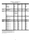
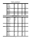
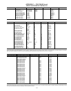
High Tiers Display Selec No = Use Navigator™
display as user interface
(factory installed)
Yes = Use Touch Pilot™
Display as user interface
(factory installed)
No highdisp
Factory Password 0 to 9999 111 fac_pass
Hydraulic Transducer Kit Yes/No No kithydro
Cooler Pass Number 1 to 3 2 cpass_nb
VLT Fan Drive Select* 0 vlt_sel
VLT Fan Drive rpm* 0 vlt_rpm
High Condensing Select Yes/No No highcond
Max Condenser LWT=45degC Yes/No No max_clwt
FACTORY2 Compressor A Config
Must Trip Amps 0 to 600 Refer to Appendix D cpa_mtac
S1 Config Switch (8 to 1) 00000000 (8 position dip
switch configuration)
Refer to Appendix D cpa_s1_c
Compressor B Config
Must Trip Amps 0 to 600 Refer to Appendix D cpb_mtac
S1 Config Switch (8 to 1) 00000000 (8 position dip
switch configuration)
Refer to Appendix D cpb_s1_c
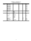
Compressor C Config
Must Trip Amps 0 to 600 0 cpc_mtac
S1 Config Switch (8 to 1) 00000000 (8 position dip
switch configuration)
0 cpc_s1_c
Circuit A Total Fans NB 2 to 8 0 nb_fan_a
Circuit B Total Fans NB 2 to 8 0 nb_fan_b
Circuit C Total Fans NB 0 to 8 0 nb_fan_c
EXV A Maximum Steps Numb 0/15000 4260 exva_max
EXV B Maximum Steps Numb 0/15000 4260 exvb_max
EXV C Maximum Steps Numb 0/15000 0 exvc_max
Economizer A Steps Numb 0/15000 2785† eco_cnfa
Economizer B Steps Numb 0/15000 2785† eco_cnfb
Economizer C Steps Numb 0/15000 0 eco_cnfc