


26
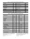
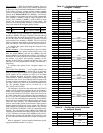
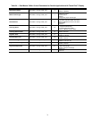
Table 22 — Cooling Set Point Selection Touch Pilot™ Parameters
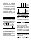
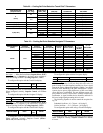
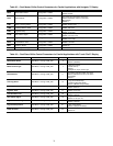
Table 23 — Cooling Set Point Selection Navigator™ Parameters
Set Point 1
— When Set Point Select (Setpoint Select, SP.SE)
is configured to 1 (Setpoint 1), the unit’s active set point is
based on Cooling Set Point 1 (Cooling Setpoint 1, CSP.1).
To configure this option with the Touch Pilot display:
To change this value, a Control Point Force must be applied.
When configured correctly, Setpoint Control will indicate
Setp 1.
To configure this option with the Navigator™ display:
Set Point 2
— When Set Point Select (Setpoint Select, SP.SE)
is configured to 2 (Setpoint 2), the unit’s active set point is
based on Cooling Set Point 2 (Cooling Setpoint 2, CSP.2).
To configure this option with the Touch Pilot™ display:
To change this value, a Control Point Force must be applied.
When configured correctly, Setpoint Control (Status
GENUNIT) will indicate Setp 2.
To configure this option with the Navigator display:
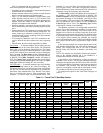
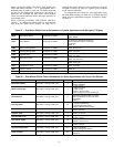
4 to 20 mA Input
— When Set Point Select (Setpoint Select,
SP.SE) is configured to 3 (4-20 mA Setp), the unit’s active set
point is based on an field supplied, external 4 to 20 mA signal
input to the Energy Management Module (EMM). Care should
be taken when interfacing with other manufacturer’s control
systems, due to power supply differences of full wave bridge
versus half wave rectification. The two different power sup-
plies cannot be mixed. ComfortLink™ controls use half wave
rectification. A signal isolation device should be utilized if a
full wave bridge signal generating device is used.
The following equation is used to control the set point. See
Fig. 18.
Fahrenheit Set Point = 10 + 70(mA – 4)/16 (deg F)
Celsius Set Point = –12.2 + 38.9(mA – 4)/16 (deg C)
To configure this option while using a Touch Pilot display:
To change this value, a Control Point Force must be applied.
When configured correctly, Setpoint Control will indicate
4-20 mA.
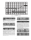
SET POINT
CONFIGURATION
(Setpoint Select)
ICE MODE
ENABLE
(ice_cnfg)
DUAL SET
POINT INPUT
(SETP_SW)
ICE DONE INPUT
(ICE_SW)
TIME
SCHEDULE 2
ACTIVE
SET POINT
0
(Auto)
NO
— — Occupied Cooling Setpoint 1
— — Unoccupied Cooling Setpoint 2
YES
— Open Unoccupied Cooling Ice Setpoint
— Closed Unoccupied Cooling Setpoint 2
— — Occupied Cooling Setpoint 1
1 (Setp 1) — — — — Cooling Setpoint 1
2 (Setp 2) — — — — Cooling Setpoint 2
3 (4-20 mA) — — — — 4 to 20 mA Input
4 (Setp Sw)
NO
Open — — Cooling Setpoint 1
Closed — — Cooling Setpoint 2
YES
Open — — Cooling Setpoint 1
Closed Open — Cooling Ice Setpoint
Closed Closed — Cooling Setpoint 2
PARAMETER STATUS
ACTIVE
SET POINT
Control Method
(OPER)
Heat/Cool
Select (HC.SE)
Setpoint
Select (SP.SE)
Ice Mode
Enable (ICE.M)
Ice Done
(ICE.D)
Dual Setpoint
Switch (DUAL)
Setpoint
Occupied
(SP.OC)
LOCAL COOL
Setpoint Occ — — — Occupied CSP.1
Setpoint Occ — — — Unoccupied CSP.2
Setpoint Occ Enable Open — Unoccupied CSP.3
Setpoint 1 — — — — CSP.1
Setpoint 2 — — — — CSP.2
4-20mA Setp — — — — 4_20mA
— Enable Open Closed — CSP.3
— Enable Closed Closed — CSP.2
— — — Open — CSP.1
Dual Setp Sw — — Closed — CSP.2
CCN COOL
— — — — Occupied CSP.1
— — — — Unoccupied CSP.2
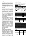
DISPLAY NAME PATH
LINE
NO.
VALUE
Setpoint Select Status GENUNIT 25 1 (Set Point 1)
ITEM ITEM EXPANSION PATH VALUE
SP.SE Setpoint Select Operating Modes SLCT Setpoint 1
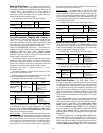
DISPLAY NAME PATH
LINE
NO.
VALUE
Setpoint Select Status GENUNIT 25 2 (Set Point 2)
ITEM ITEM EXPANSION PATH VALUE
SP.SE Setpoint Select Operating Modes SLCT Setpoint 2
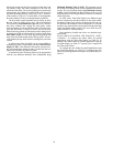
DISPLAY NAME PATH
LINE
NO.
VALUE
Setpoint Select Status GENUNIT 25 3 (4-20 mA Input)