


45
Override #14: Slow Change Override
— This override pre-
vents compressor stage changes when the leaving temperature
is close to the control point and slowly moving towards it.
Override #15: System Manager Capacity Control
— If a
Chillervisor module is controlling the unit and multiple chill-
ers, the unit will increase capacity to attempt to load to the de-
mand limited value.
Override #16: Circuit A High Pressure Override
Override #17: Circuit B High Pressure Override — This
override attempts to avoid a high pressure failure. The algo-
rithm is run every 4 seconds. If the Saturated Condensing Tem-
perature for the circuit is above the High Pressure Threshold
(High Pressure Threshold, HP.TH) then the position of slide
valve will be unloaded.
Override #19: Standby Mode
— This override algorithm will
not allow a compressor to run if the unit is in Standby mode,
(Heat/Cool Status, HC.ST=2).
Override #22: Minimum On Time Delay
— In addition to
Override #13 Minimum On/Off and Off/On Time Delay, for
compressor capacity changes, an additional 90-second delay
will be added to Override #13 delay. No compressor will be
deenergized until 3 minutes have elapsed since the last com-
pressor has been turned ON. When this override is active, the
capacity control algorithm calculations will be performed, but
no capacity reduction will be made until the timer has expired.
A control with higher precedence will override the Minimum
On Time Delay.
Override #23: Circuit A Low Saturated Suction Tempera-
ture in Cooling
Override #24: Circuit B Low Saturated Suction Tempera-
ture in Cooling — If the circuit is operating close to the opera-
tional limit of the compressor, the circuit capacity will remain at
the same point or unload to raise the saturated suction tempera-
ture. This algorithm will be active if at least 1 compressor in the
circuit is on and one of the following conditions is true:
1. Saturated Suction Temperature is less than the Brine
Freeze Setpoint (Brine Freeze Setpoint, LOSP) –6º F
(3.3º C).
2. Saturated Suction Temperature is less than the Brine
Freeze Setpoint (Brine Freeze Setpoint, LOSP) and the
circuit approach (Leaving Water Temperature – Saturated
Suction Temperature) is greater than 15º F (8.3º C) and
the Circuit Superheat (Discharge Gas Temperature – Sat-
urated Discharge Temperature) is greater than 25º F
(13.9º C).
NOTE: The freeze set point is 34 F (1.1 C) for fresh
water systems (Cooler Fluid Type, FLUD=1). The
freeze set point is Brine Freeze Set Point (Brine Freeze
Setpoint, LOSP), for Medium Temperature Brine
systems (Cooler Fluid Type, FLUD=2).
If any of these conditions are met, the appropriate operating
mode, 21 (Circuit A) or 22 (Circuit B) will be in effect.
Override #34: Circuit A Low Refrigerant Charge
Override #35: Circuit B Low Refrigerant Charge — The ca-
pacity override attempts to protect the compressor from start-
ing with no refrigerant in the circuit. This algorithm runs only
when the circuit is not operational (compressors is OFF). There
are several criteria that will enable this override:
1. The saturated suction temperature or saturated discharge
temperature is less than –13 F (–25 C).
2. All of these conditions must be true:
a. The saturated suction temperature or saturated
discharge temperature is less than leaving fluid
temperature by more than 5.4º F (3.0º C).
b. Saturated suction temperature or saturated dis-
charge temperature is less than 41 F (5 C).
c. Outdoor air temperature is less than 32 F (0º C).
d. Saturated suction temperature or saturated discharge
temperature is less than the outdoor air temperature
by more than 5.4º F (3.0º C).
3. All of these conditions must be true:
a. The saturated suction temperature or saturated
discharge temperature is less than leaving fluid
temperature by more than 5.4º F (3.0º C).
b. Saturated suction temperature or saturated dis-
charge temperature is less than 41 F (5 C).
c. Saturated suction temperature or saturated dis-
charge temperature is less than the brine freeze
point (Brine Freeze Setpoint, LOSP) by more
than 6º F (3.3º C).
NOTE: The freeze set point is 34 F (1.1 C)
for fresh water systems (Brine Freeze Setpoint,
FLUD=1). The freeze set point is brine freeze set
point (Brine Freeze Setpoint, LOSP), for medium
temperature brine systems (Cooler Fluid Type,
FLUD=2).
4. All of these conditions must be true:
a. The saturated suction temperature or saturated
discharge temperature is less than leaving water
temperature by more than 5.4º F (3.0º C).
b. Saturated suction temperature or saturated discharge
temperature is less than 41 F (5 C).
c. Saturated suction temperature or saturated discharge
temperature is less than the outdoor-air temperature
by more than 9º F (5º C).
If any of these conditions 1, 2, 3 or 4 are met, the appropri-
ate operating mode, 21 (Circuit A) or 22 (Circuit B) will be in
effect.
Override #41: Circuit A High Current Override
Override #42: Circuit B High Current Override — This
override attempts to avoid an overcurrent failure. The algo-
rithm is run every 4 seconds. If the compressor current is great-
er than 79% of must trip amps (MTA) but less than 85% MTA
then the capacity will be held at current capacity. If the com-
pressor current is greater than 85% MTA then capacity will be
reduced by repositioning the slide valve until the current is less
than 85% MTA (Must Trip Amps, MTA.X).
Override #44: Circuit A High Suction Superheat at Part
Load
Override #45: Circuit B High Suction Superheat at Part
Load — If the compressor of the circuit is on, the compressor
current is no more than 30% of the MTA, main EXV is more
than 90% open and the suction superheat is higher than the
superheat control point for more than 5 minutes, then the cir-
cuit will be shut down.
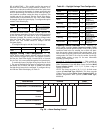
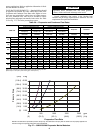
Override #53: Circuit A Delay for Unloading the Slide
Val ve
Override #54: Circuit B Delay for Unloading the Slide
Val ve — This override prevents the compressor from re-start-
ing with locked rotor failure after being shutdown due to an
alarm or power cycle. The delay varies depending on the size
of the compressor. Refer to Table 34 for compressor nominal
capacities. A delay of 20 minutes will elapse for 182 and
204 ton compressors. The delay allows the slide valve of the
compressor to move back to its fully unloaded position. The
delay is adjusted according to the percent of the compressor
running capacity before it is shut down. If the compressor is
stopped normally, no delay will be applied. If the compressor is
shut down by the locked rotor alarm, a full delay will be ap-
plied before the compressor is allowed to re-start.