


56
If this condition is encountered, see Possible Causes for
Alarms 56 and 57 on page 75.
HIGH DGT CIRCUIT A
HIGH DGT CIRCUIT B — The capacity of the affected
circuit may be increased to reduce circuit discharge gas
temperature.
HIGH PRES OVERRIDE CIR A
HIGH PRES OVERRIDE CIR B — This mode is checked
for when the circuit is ON. The appropriate circuit mode will
be active if the discharge pressure for the circuit, Discharge
Pressure Circuit A (Discharge Pressure, DP.A), Discharge
Pressure Circuit B (Discharge Pressure, DP.B), or Discharge
Pressure Circuit C (Discharge Pressure, DP.C), is greater than
the High Pressure Threshold (High Pressure Threshold,
HP.TH).
The capacity of the affected circuit will be reduced. Two
minutes following the capacity reduction, the circuit’s saturated
condensing temperature (SCT
t+2
) is calculated and stored. The
affected circuit will not be allowed to add capacity for at least 5
minutes following the capacity reduction. If after 5 minutes,
the circuit’s saturated condensing temperature is less than
SCT
t+2
–3° F (1.7° C), and then if required, percent capacity
will be added. If additional capacity is required, the control will
look for other circuits to add capacity.
This mode will terminate once the circuit’s saturated con-
densing temperature is less than SCT
t+2
–3° F (1.7° C).
If this condition is encountered, see Possible Causes for
Alarm A1.03. on page 81.
LOW SUPERHEAT CIRCUIT A
LOW SUPERHEAT CIRCUIT B — This mode is checked
for when the circuit is ON. The appropriate circuit mode will
be active if the circuit’s superheat (discharge gas temperature
— SCT) is less than 18° F (10° C).
No additional capacity will be added until the circuit’s su-
perheat is greater than 18° F (10° C). The control will look for
other circuits to add capacity if additional steps of capacity are
required. This mode will terminate once the affected circuit’s
superheat is greater than 18° F (10° C).
If this condition is encountered, see Possible Causes for
Alarms P.11 and P.12 on page 77.
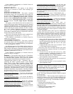
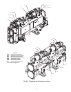
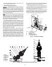
Sensors — The electronic control uses up to 13 thermistors
to sense temperatures and up to 8 transducers to sense pressure
for controlling chiller operation. These sensors are outlined
below. See Fig. 38 for thermistor and transducer locations.
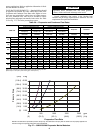
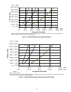
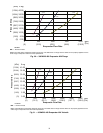
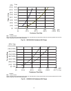
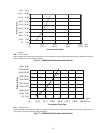
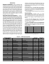
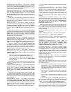
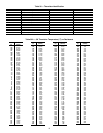
THERMISTORS (Tables 38-39B) — Thermistors that are
monitoring the chiller’s operation include: Cooler Entering
Water, Cooler Leaving Water, Condenser Entering Water,
Condenser Leaving Water, Dual Chiller Leaving Water, Com-
pressor Suction Gas Temperature, Compressor Discharge Gas
Temperature, Economizer Temperature, and Compressor Motor
Temperature. These thermistors are 5 kat 77 F (25 C) and are
identical in temperature versus resistance. The Space Tempera-
ture Thermistor is 10 kat 77 F (25 C) and has a different tem-
perature vs. resistance. See Fig. 38 for thermistor locations.
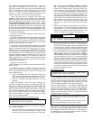
Cooler Leaving Water Sensor
— On all sizes, this thermistor
is installed in a well in the leaving water nozzle of the cooler.
See Fig. 39 and 40.
Cooler Entering Water Sensor
— On all sizes, this thermis-
tor is factory-installed in a well in the entering water nozzle of
the cooler.
Condenser Leaving Water Sensor —
On all sizes with heat
machine options, this thermistor is installed in a well in the
leaving water nozzle of the condenser. See Fig. 39 and 40.
Condenser Entering Water Sensor
— On all sizes with heat
machine options, this thermistor is factory-installed in a well in
the entering water nozzle of the condenser.
Compressor Suction Gas Temperature
— On all sizes, this
thermistor is factory-installed in a well located on the compres-
sor of each circuit. There is one thermistor for each circuit.
Compressor Discharge Gas Temperature
— On all sizes, this
thermistor is factory-installed in a well located in the discharge
end of the compressor for the circuit. There is one thermistor
for each circuit.
Economizer Temperature
(sizes 175,200,350,400 only) —
On all sizes, this thermistor is factory-installed in a friction fit
well located in the economizer line for the circuit. There is one
thermistor for each circuit.
Compressor Motor Temperature
— On all sizes, this therm-
istor is embedded in the motor windings. There are two therm-
istors in each compressor. One spare is provided.
Remote Space Temperature
— This sensor (part no.
33ZCT55SPT) is a field-installed accessory mounted in the in-
door space and is used for water temperature reset. The sensor
should be installed as a wall-mounted thermostat would be (in
the conditioned space where it will not be subjected to either a
cooling or heating source or direct exposure to sunlight, and 4
to 5 ft above the floor).
Space temperature sensor wires are to be connected to
terminals in the unit main control box. The space temperature
sensor includes a terminal block (SEN) and a RJ11 female con-
nector. The RJ11 connector is used to access the Carrier Com-
fort Network
®
(CCN) system at the sensor. See Fig. 39 and 40.
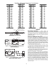
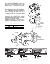
To connect the space temperature sensor (see Fig. 41):
1. Using a 20 AWG twisted pair conductor cable rated for
the application, connect one wire of the twisted pair to
one SEN terminal and connect the other wire to the other
SEN terminal located under the cover of the space
temperature sensor.
2. Connect the other ends of the wires to terminals 7 and 8
on TB6 located in the unit control box.
Units on the CCN can be monitored from the space at the
sensor through the RJ11 connector, if desired. To wire the RJ11
connector into the CCN:
1. Cut the CCN wire and strip ends of the red (+), white
(ground), and black (–) conductors. (If another wire color
scheme is used, strip ends of appropriate wires.)
2. Insert and secure the red (+) wire to terminal 5 of the
space temperature sensor terminal block.
3. Insert and secure the white (ground) wire to terminal 4 of
the space temperature sensor.
4. Insert and secure the black (–) wire to terminal 2 of the
space temperature sensor.
5. Connect the other end of the communication bus cable to
the remainder of the CCN communication bus.
NOTE: The Energy Management Module (EMM) is required
for this accessory.
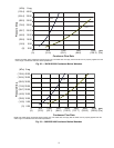
TRANSDUCERS — There are four pressure transducers per
circuit (3 per circuit for sizes 150,325), and two different types
of transducers: low pressure (green connector) and high pres-
sure (black connector). See Fig. 38 for transducer locations.
Low-pressure type:
• Suction pressure transducer (SPT)
• Economizer pressure transducer (EPT)
High-pressure type:
• Discharge pressure transducer (DPT)
• Oil pressure transducer (OPT)
IMPORTANT: The cable selected for the RJ11
connector wiring MUST be identical to the CCN
communication bus wire used for the entire network.
Refer to Table 11 for acceptable wiring.