


63
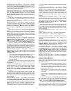
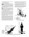
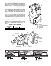
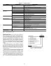
Compressor Assembly — The 30XW units utilize
screw compressors with a modulating slide valve which varies
capacity from 15% to 100% of compressor capacity for each
circuit. See Fig. 45 for a view of a typical 06T compressor.
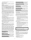
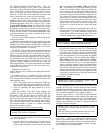
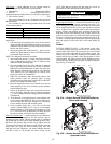
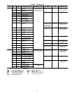
The slide valve position is varied by opening and closing the
2 solenoid valves located on the compressor. To unload the
compressor, both solenoids are deenergized. To increase in
capacity both solenoid valves are energized together which
will cause the slide valve to slide towards the fully loaded posi-
tion. To stop the loading process solenoid 2 is energized and
solenoid 1 is deenergized. This will cause the slide valve to
maintain its current position. There is no feedback for the posi-
tion of the slide valve. The control utilizes compressor current
as an indicator of the slide valve position. Once the calculated
position of the slide valve reaches 100% circuit capacity, the
control will try to increase capacity again if the compressor
current continues to increase. The control will continue to load
the compressor until the compressor current no longer
increases. At that time the control will energize both solenoids
and the circuit will be considered fully loaded.
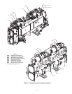
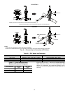
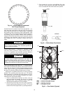
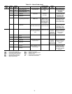
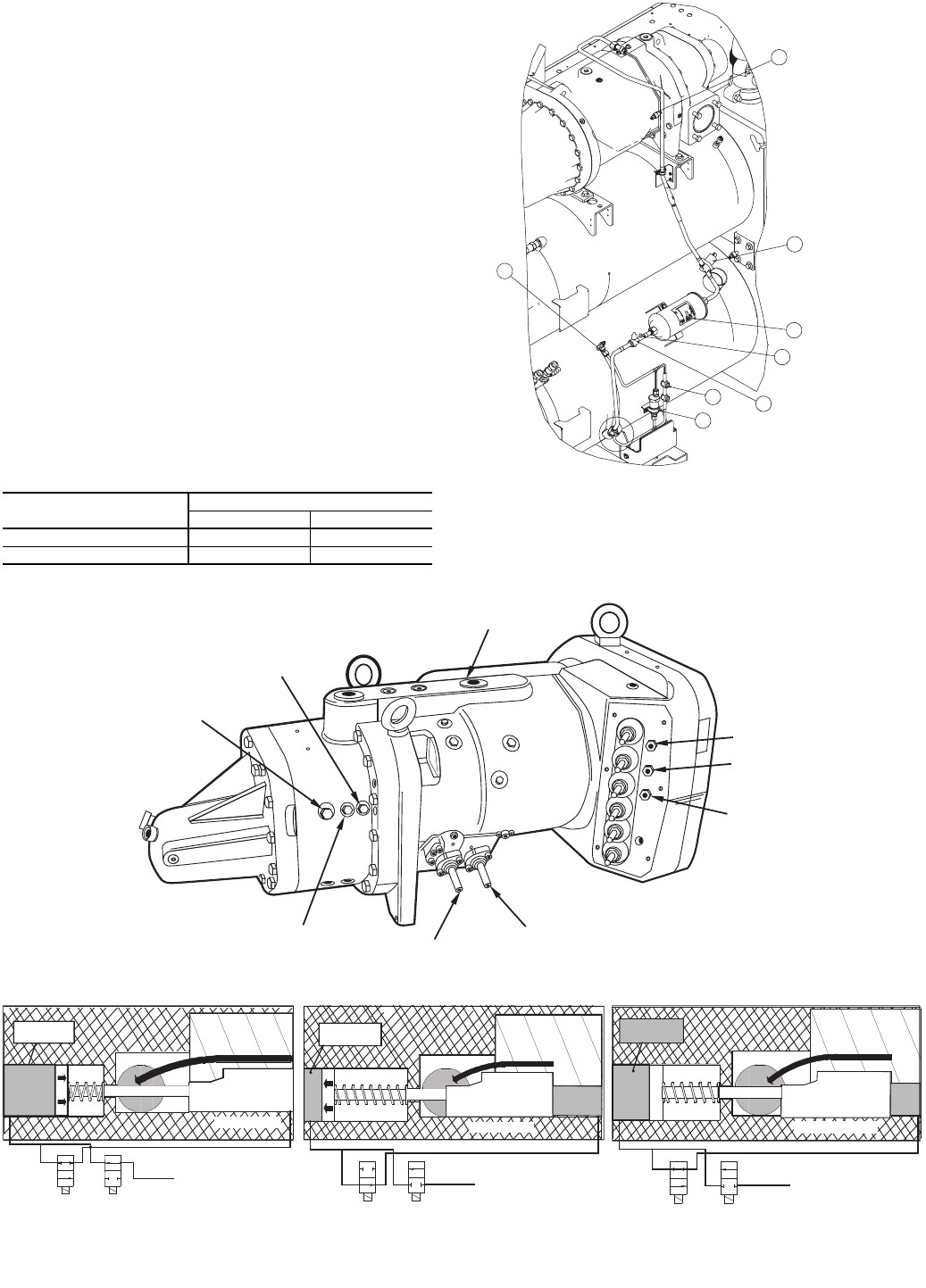
COMPRESSOR OIL SYSTEM — Each compressor/circuit
has its own oil system which includes an oil filter, oil solenoid,
check valve, oil level switch, oil pressure transducer, and an oil
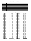
shut-off valve. A typical oil system is shown in Fig. 46. See
Table 42.
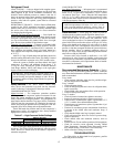
Table 42 — Unit Oil Quantities
30XW UNIT SIZE
OIL CHANGE (gal, [liters])
Circuit A Circuit B
150-200 6.0 [22.7] —
325-400 5.0 [18.9] 5.0 [18.9]
Fig. 45 — Typical 06T Compressor
SOLENOID 1
SOLENOID 2
HIGH PRESSURE
SWITCH
MOTOR TEMPERATURE
SENSOR 2
COMMON
MOTOR TEMPERATURE
SENSOR 1
t e x t
C o m p r e s s i o n
P r o c e s
s
H i g h P r e s s u r e O i l
D e - e n e r g i z e d
F L O W
V a l v e # 2 ( N O )
D e - e n e r g i z e d
N O F L O W
V a l v e # 1 ( N C )
B l e e d L i n e t o L o w P r e s s u r e S u c t i o n
l
D i s c h a r g e
P o r
t
U n l o a d e r P i s t o n
C h a m b e
r
t e x t
C o m p r e s s i o n
P r o c e s s
L o a d e d P o s i t i o
n
H i g h P r e s s u r e O i l
E n e r g i z e d
N O F L O W
V a l v e # 2 ( N O )
E n e r g i z e d
F L O W
V a l v e # 1 ( N C )
B l e e d L i n e t o L o w P r e s s u r e S u c t i o n
S l i d e V a l v e
D i s c h a r g e
P o r
t
U n l o a d e r P i s t o n
C h a m b e
r
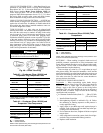
Loaded Position
High with
High
Pressure
Oil
Drain to
Low Pressure
Unloaded Position
Slide Valve
t e x t
H i g h P r e s s u r e O i l
T r a p p e d
O i l a t
H i g h
P r e s s u r
e
C o m p r e s s i o n
P r o c e s s
P a r t L o a d P o s i t i o n
E n e r g i z e d
N O F L O W
V a l v e # 2 ( N O )
D e - e n e r g i z e d
N O F L O W
V a l v e # 1 ( N C )
B l e e d L i n e t o L o w P r e s s u r e S u c t i o n
S l i d e V a l v e
D i s c h a r g e
P o r t
U n l o a d e r P i s t o n
C h a m b e
r
Slide Valve
FULLY LOADED OPERATION
FULLY UNLOADED OPERATION
MAINTAIN POSITION
DISCHARGE
GAS THERMISTOR
ACCESS
FITTING
SUCTION
TEMPERATURE
A30-4841
1
2
3
4
5
6
7
8
Fig. 46 — Typical Oil System
A30-4842
LEGEND
1—Oil Pressure Transducer
2—Oil Solenoid
3—Oil Filter
4—
1
/
4
in. FL (Female) Access Fitting
5—Shut-Off Valve
6—Oil Level Sight Glass
7—Oil Level Switch
8—
1
/
4
in. FL (Female) Access Fitting