


65
LOW FLUID TEMPERATURE — Main Base Board is pro-
grammed to shut chiller down if leaving fluid temperature
drops below 34 F (1.1 C) for cooler fluid type water or below
Brine Freeze Setpoint (Brine Freeze Setpoint, LOSP) for
cooler fluid type brine. The unit will shut down without a
pumpout. When fluid temperature rises to 6° F (3.3° C) above
the leaving fluid set point, safety resets and chiller restarts.
Reset is automatic as long as this is the first occurrence.
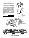
LOSS OF FLUID FLOW PROTECTION — All 30XW ma-
chines include an integral flow switch that protects the cooler
against loss of cooler flow. In addition, all models ordered for
heat reclaim duty have factory installed condenser water sen-
sors and an integral flow switch.
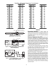
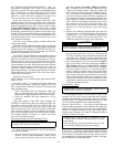
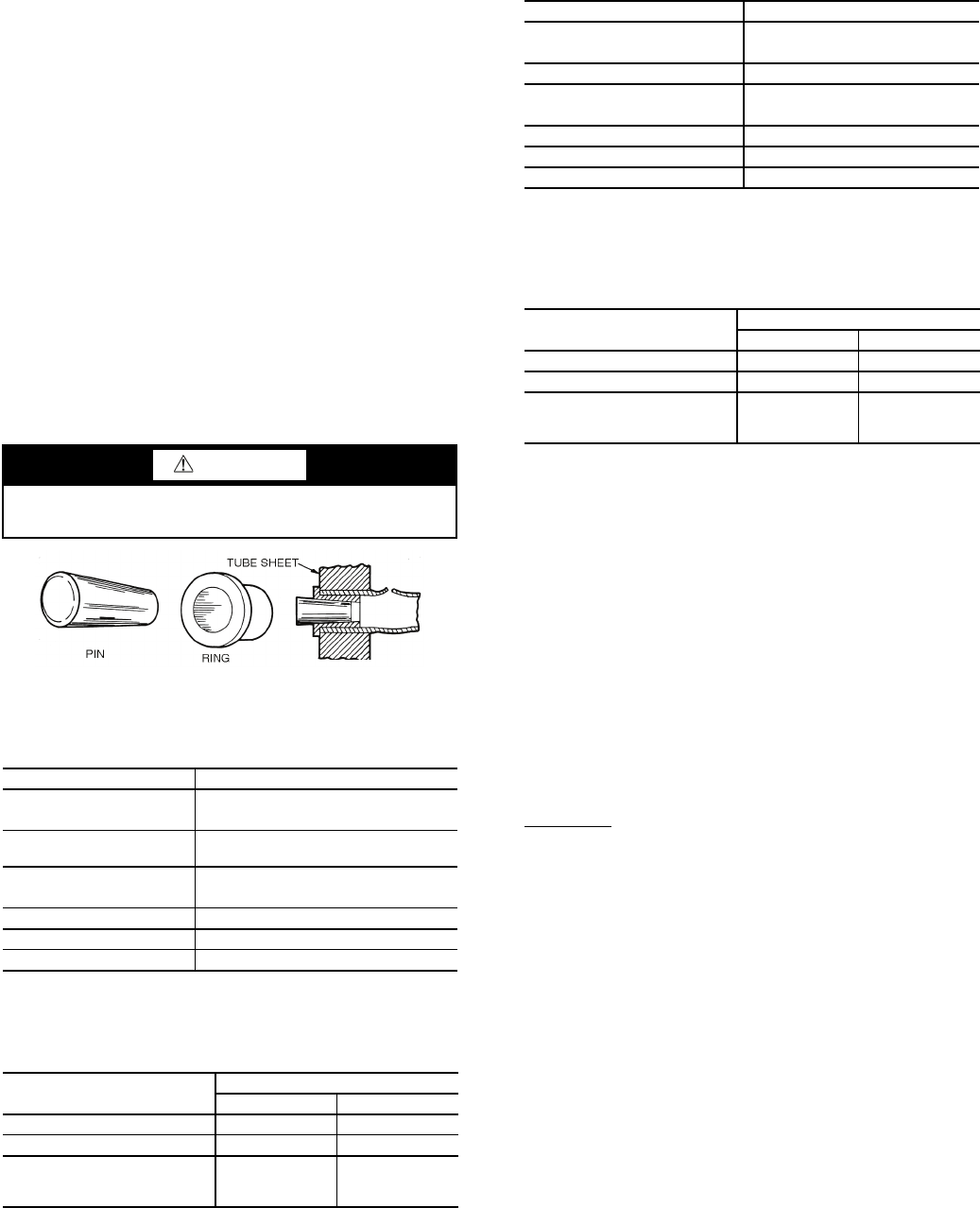
TUBE PLUGGING — A leaky tube can be plugged until
retubing can be done. The number of tubes plugged determines
how soon the cooler must be retubed. All tubes in the cooler
may be removed. Loss of unit capacity and efficiency as well
as increased pump power will result from plugging tubes.
Failed tubes should be replaced as soon as possible. Up to 10%
of the total number of tubes per pass can be plugged before
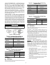
retubing is necessary. Fig. 48 shows an Elliott tube plug and a
cross-sectional view of a plug in place. See Tables 43-46 for
plug components. If the tube failure occurs in both circuits
using tube plugs will not correct the problem. Contact your
local Carrier representative for assistance.
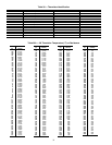
Table 43 — Condenser (Sizes 150-200) and
Evaporator Plug Component Parts
*Order directly from Elliot Tube Company, Dayton, OH or RCD.
†Can be obtained locally.
Table 44 — Condenser (Sizes 150-200) and
Evaporator Tube Components
LEGEND
NOTE: Tubes replaced along heat exchanger head partitions must
be flush with tube sheet (both ends).
Table 45 — Condenser (Sizes 325-400) Plug
Component Parts
*Order directly from Elliot Tube Company, Dayton, OH or RCD.
†Can be obtained locally.
Table 46 — Condenser (Sizes 325-400) Tube
Components
LEGEND
NOTE: Tubes replaced along heat exchanger head partitions must
be flush with tube sheet (both ends).
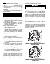
RETUBING — When retubing is required, obtain service of
qualified personnel experienced in boiler maintenance and
repair. Most standard procedures can be followed when retub-
ing the coolers. An 8% crush is recommended when rolling
replacement tubes into the tubesheet.
Place one drop of Loctite No. 675 or equivalent on top of
tube prior to rolling. This material is intended to “wick” into the
area of the tube that is not rolled into the tube sheet, and prevent
fluid from accumulating between the tube and the tube sheet.
New tubes must also be rolled into the center tubesheet to
prevent circuit to circuit leaks.
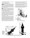
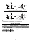
TIGHTENING COOLER HEAD BOLTS
Preparation
— When reassembling cooler heads, always
check the condition of the O-rings first. The O-ring should be
replaced if there is visible signs of deterioration, cuts or
damage. Apply a thin film of grease to the O-ring before
installation. This will aid in holding the O-ring in the groove
while the head is installed. Torque all bolts to the following
specification and in sequence:
3
/
4
-in. Diameter Perimeter Bolts (Grade 5) . . . 200 to 225 ft-lb
(271 to 305 N-m)
1. Install all bolts finger tight.
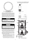
2. Bolt tightening sequence is outlined in Fig. 49. Follow
the numbering or lettering sequence so that pressure is
evenly applied to O-ring.
3. Apply torque in one-third steps until required torque is
reached. Load all bolts to each one-third step before pro-
ceeding to next one-third step.
4. No less than one hour later, retighten all bolts to required
torque values.
5. After refrigerant is restored to system, check for refriger-
ant leaks using recommended industry practices.
6. Replace cooler insulation.
CAUTION
Use extreme care when installing plugs to prevent damage
to the tube sheet section between the holes.
COMPONENT PART NUMBER
For Tubes
Brass Pin 853103-1*
Brass Ring 853002-657 or 670* (Measure inside
diameter of tube before ordering.)
For Holes without Tubes
Brass Pin 853103-1A*
Brass Ring 853002-738*
Loctite No. 675†
Locquic “N”†
COMPONENT
SIZE
in. mm
Tube Sheet Hole Diameter 0.752 to 0.757 19.10 to 19.23
Tube OD 0.742 to 0.748 18.85 to 19.00
Tube ID after Rolling
(includes expansion due to
clearance.)
0.666 to 0.681 16.92 to 17.30
ID — Inside Diameter
OD — Outside Diameter
COMPONENT PART NUMBER
For Tubes
Brass Pin 853103-2A*
Brass Ring 853002-918*
For Holes without tubes
Brass Pin 853103-3*
Brass Ring 853002-988*
Loctite No. 675†
Locquic “N”†
COMPONENT
SIZE
in. mm
Tube Sheet Hole Diameter 1.000 to 1.008 25.40 to 25.60
Tube OD 0.992 to 0.998 25.20 to 25.35
Tube ID after Rolling
(includes expansion due to
clearance.)
0.918 to 0.935 23.32 to 23.75
ID — Inside Diameter
OD — Outside Diameter
Fig. 48 — Elliott Tube Plug
a30-4083