


67
Refrigerant Circuit
LEAK TESTING — Units are shipped with complete operat-
ing charge of refrigerant R-134a or nitrogen (see Physical Data
tables supplied in the 30XW installation instructions) and
should be under sufficient pressure to conduct a leak test. If
there is no pressure in the system, introduce enough nitrogen to
search for the leak. Repair the leak using good refrigeration
practices. After leaks are repaired, system must be evacuated
and dehydrated.
REFRIGERANT CHARGE — Refer to Physical Data tables
supplied in the 30XW installation instructions. Immediately
ahead of filter drier in each circuit is a factory-installed liquid
line service valve. Each valve has a
1
/
4
-in. access connection
for charging liquid refrigerant.
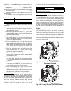
Charging with Unit Off and Evacuated
— Close liquid line
service valve before charging. Weigh in charge shown on unit
nameplate. Open liquid line service valve; start unit and allow
it to run several minutes fully loaded. Check for a clear sight
glass. Be sure clear condition is liquid and not vapor.
Charging with Unit Running
— If charge is to be added while
unit is operating, loop water temperatures should be near the
ARI rating point (54/44 F evaporator; 85/95 F condenser). At
these conditions and with the circuit at full load, charge to a
clear sightglass and a liquid line temperature of 90 to 93 F (32.2
to 33.9 C).
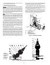
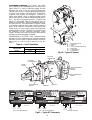
Add 5 lb (2.3 kg) of liquid charge into the fitting located on
the tube entering the bottom of the cooler. This fitting is located
between the electronic expansion valve (EXV) and the cooler.
Allow the system to stabilize and then recheck the liquid
temperature. If needed, add additional liquid charge, 5 lb
(2.3 kg) at a time, allowing the system to stabilize between
each charge addition. Slowly add charge as the sight glass
begins to clear to avoid overcharging.
Safety Devices — The 30XW chillers contain many
safety devices and protection logic built into the electronic
control. Following is a description of the major safeties.
COMPRESSOR PROTECTION
Motor Overload
— The compressor protection modules
(CPM) protect each compressor against overcurrent. Do not
bypass the current transducers or make any changes to the
factory-installed and configured headers. The configuration of
these headers defines the Must Trip Amps (MTA) at which the
CPM will turn the compressors off. Determine the cause for
trouble and correct the problem before resetting the CPM. See
Appendix D for MTA settings and configuration headers.
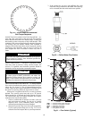
Each CPM board also reads the status of each compressor’s
high-pressure switch. All compressors have factory-installed
high-pressure switches. See Table 47.
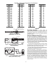
Table 47 — High-Pressure Switch Settings
If the switch opens during operation, the compressor will be
shut down. The CPM will reset automatically when the switch
closes, however, a manual reset of the control is required to
restart the compressor.
COOLER PROTECTION
Low Water Temperature
— Microprocessor is programmed
to shut the chiller down if the leaving fluid temperature drops
below 34 F (1.1 C) for water or more than 8 F (4.4 C) below
set point for Fluid Type = brine. When the fluid temperature
rises 6 F (3.3 C) above the leaving fluid set point, the safety
resets and the chiller restarts. Reset is automatic as long as this
is the first occurrence of the day.
Relief Devices — Fusible plugs are located in each cir-
cuit between the condenser and the liquid line shutoff valve.
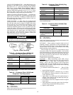
PRESSURE RELIEF VALVES — Valves are installed in each
circuit and are located on all coolers and condensers. These
valves are designed to relieve if an abnormal pressure condition
arises. Relief valves on all coolers relieve at 220 psi (1517 kPa).
These valves should not be capped. If a valve relieves, it should
be replaced. If the valve is not replaced, it may relieve at a lower
pressure, or leak due to trapped dirt from the system which may
prevent resealing. Valves on standard condensers relieve at
220 psi (1517 kPa). Valves on high condensing and heat reclaim
units relieve at 300 psi (2068 kPa).
Pressure relief valves located on shells have
3
/
4
-in. NPT
connections for relief. Some local building codes require that
relieved gases be exhausted to a specific location. This connec-
tion allows conformance to this requirement. Refer to Installa-
tion Instructions for details.
MAINTENANCE
Recommended Maintenance Schedule —
The fol-
lowing are only recommended guidelines. Jobsite conditions
may dictate that maintenance schedule is performed more often
than recommended.
Every month:
• Check moisture indicating sight glass for possible refriger-
ant loss and presence of moisture.
Every 3 months:
• Check refrigerant charge.
• Check all refrigerant joints and valves for refrigerant leaks;
repair as necessary.
• Check chilled water and condenser flow switch operation.
• Check oil filter pressure drop.
Every 12 months:
• Check all electrical connections; tighten as necessary.
• Inspect all contactors and relays; replace as necessary.
• Check accuracy of thermistors; replace if greater than ±2° F
(1.2° C) variance from calibrated thermometer.
• Check accuracy of transducers; replace if greater than ±5 psi
(34.47 kPa) variance.
• Check to be sure that the proper concentration of antifreeze
is present in the chilled water and condenser loops, if
applicable.
• Verify that the chilled water loop is properly treated.
• Check refrigerant filter driers for excessive pressure drop;
replace as necessary.
• Check chilled water and condenser strainers, clean as
necessary.
• Perform Service Test to confirm operation of all components.
• Check for excessive cooler approach (Leaving Chilled
Water Temperature – Saturated Suction Temperature) which
may indicate fouling. Clean cooler vessel if necessary.
• Obtain oil analysis; change as necessary.
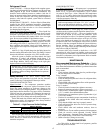
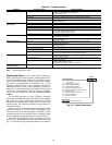
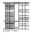
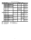
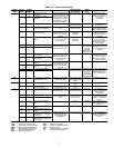
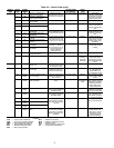
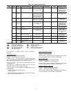
TROUBLESHOOTING
See Table 48 for an abbreviated list of symptoms, possible
causes and possible remedies.
IMPORTANT: When adjusting refrigerant charge, circu-
late fluid through cooler and condenser continuously to
prevent freezing and possible damage to both. Do not
overcharge, and never charge liquid into the low-pressure
side of system.
30XW UNIT
SWITCH SETTING
psig kPa
STD 217.6 +7.25, –14.5 1500 +50, –100
HIGH COND 304.5 +7.25, –14.5 2099 +50, –100
IMPORTANT: If unit is installed in an area where
ambient temperatures fall below 32 F (0° C), a suit-
able corrosion-inhibited antifreeze solution must be
used in the chilled water and condenser water circuit.