


83
Possible Causes — If this condition is encountered, check the
following items:
• electrical noise
• faulty CPM board
Compressor UL 1998 Current Measure Dual Channel Mismatch
Alarm 132-19 — Circuit A (A1.19)
Alarm 133-19 — Circuit B (B1.19)
Criteria for Trip — The alarm criterion is checked when the
compressor is ON. This alarm will be generated if the CPM
board detects a software error.
Action to be Taken — The compressor will be stopped.
Reset Method — Manual
Possible Causes — If this condition is encountered, check the
following items:
• electrical noise
• faulty CPM board
Service Test — Main power and control circuit power
must be on for Service Test.
The Service Test function is used to verify proper operation
of various devices within the chiller, such as compressors, min-
imum load valve solenoid (if installed), cooler pump(s) and re-
mote alarm relay. This is helpful during the start-up procedure
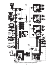
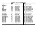
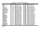
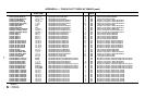
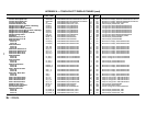
to determine if devices are installed correctly. See Fig. 53 for
30XW wiring diagram.
SERVICE TEST WITH NAVIGATOR™ DISPLAY — To
use the Service Test mode, the Enable/Off/Remote Contact
switch must be in the OFF position. Use the display keys to
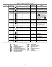
move to the Service Test mode. The items are described in the
Service Test table. There are two sub-modes available. Service
Test Enable, T.REQ allows for manual control of the compres-
sors and minimum load control. In this mode the compressors
will operate only on command. The capacity control, head
pressure control, and EXV control algorithms will be active.
There must be a load on the chiller to operate for an extended
period of time. All circuit safeties will be honored during the
test. Quick Test Enable, Q.REQ allows for test of EXVs,
pumps, oil solenoids, unloader solenoids and status points
(alarm relays, running status and chiller capacity). If there are
no keys pressed for 5 minutes, the active test mode will be
disabled.
To enter the Manual Control mode with the Navigator™
display, the Enable/Off/Remote Contact switch must be in the
OFF position. Move the LED to the Service Test mode. Press
to access TEST. Press to access T.REQ.
Press and the display will show OFF. Press
and OFF will flash. Enter the password if required.
Use either arrow key to change the T.REQ value to ON and
press . Place the Enable/Off/Remote Switch in the
enable position. Manual Control mode is now active. Press the
arrow keys to move to the appropriate item. To activate an item
locate the item, press and the display will show OFF.
Press and OFF will flash. Use either arrow key to
change the value to ON and press . The item should
be active. To turn the item off, locate the item, press
and the display will show ON. The chiller must be enabled by
turning the Enable/Off/Remote Contact switch to Enable. Press
and ON will flash. Use either arrow key to change
the value to OFF and press . The item should be
inactive.
To enter the Quick Test mode, the Enable/Off/Remote
Contact switch must be in the OFF position. Move the LED to
the Service Test mode. Press to access TEST. Use
the key until the display reads QUIC. Press to
access Q.REQ. Press and the display will show OFF.
Press and OFF will flash. Enter the password if
required. Use either arrow key to change the QUIC value to
ON and press . Quick Test mode is now active. Fol-
low the same instructions for the Manual Control mode to acti-
vate a component.
Example — Test the oil solenoid circuit A (see Table 53).
Power must be applied to the unit. Enable/Off/Remote
Contact switch must be in the OFF position.
Test the cooler pump(s) and alarm relay by changing the
item values from OFF to ON. These discrete outputs are then
turned off if there is no keypad activity for 10 minutes. Test the
compressor and minimum load valve solenoid (if installed)
outputs in a similar manner. The minimum load valve sole-
noids will be turned off if there is no keypad activity for
10 minutes. Compressors will stay on until the operator turns
them off. The Service Test mode will remain enabled for as
long as there is one or more compressors running. All safeties
are monitored during this test and will turn a compressor, cir-
cuit or the machine off if required. Any other mode or sub-
mode can be accessed, viewed, or changed during the Manual
Control mode only. The STAT item (Run Status VIEW) will
display “0” as long as the Service mode is enabled. The TEST
sub-mode value must be changed back to OFF before the chill-
er can be switched to Enable or Remote contact for normal
operation.
NOTE: There may be up to a one-minute delay before the
selected item is energized.
SERVICE TEST WITH TOUCH PILOT™ DISPLAY —
To enter the Manual Control mode with the Touch Pilot dis-
play, the unit Operating Type must be Local OFF. Use the
START/STOP button on the Touch Pilot display to stop the
machine if necessary. To place the unit the Service Test mode,
select Main Menu STATUS Page Down SERV_TST
and configure Service Test Enable to YES. Enter the pass-
word if required. Configure the desired compressor output to
ON. Then press the START/STOP button on the Touch Pilot
dispaly and select Local on. Return to the SERV_TST screen
to start and stop compressors or manually operate the compres-
sor slide valve.
To enter the Quick Test mode, the unit Operating Type must
be Local OFF. Use the START/STOP button on the Touch Pilot
display to stop the machine if necessary. To place the unit in
Quick Test mode select Main Menu STATUS Page
Down QCK_TST1 and configure Quick Test Enable to Yes.
Enter the password if required. Configure the desired output to
ON, percent output or stage to confirm operation of the
component.
ENTER
ENTER
ENTER
ENTER
ENTER
ENTER
ENTER
ENTER
ENTER
ENTER
ENTER
ENTER
ENTER
ENTER
ENTER
ENTER