


20
LIMITED ACCESS PANEL — This configuration is used to
specify the limited access password.
Allowable Entries: 0 through 9999
Default Value: 2222
ACTIVE LANGUAGE — This configuration is used to spec-
ify the display’s active language. All translatable text will be
displayed in this language.
Allowable Entries: 0 (English), 1 (alternate, installed by user)
Default Value: 0
TIME FORMAT — This configuration is used to specify the
format for display of time.
Allowable Entries: 0 = H:MM AM/PM without leading zero
1 = HH:MM with leading zero when
necessary
Default Value: 0
DATE FORMAT — This configuration is used to specify the
format for display of date.
Allowable Entries: 0 = MM-DD-YYYY with leading zero
when necessary
1 = DD-MM-YYYY with leading zero
when necessary
2 = YYYY-MM-DD
Default Value: 0
UNITS BASE — This configuration is used to specify the for-
mat of the units of measure.
Allowable Entries: U.S.
Metric
Default Value: U.S.
CONTRAST CONTROL — This configuration is used to en-
able or disable the display’s auto contrast adjustment feature.
When enabled, the display’s contrast will be automatically ad-
justed as required, based on temperature.
Allowable Entries: Manual
(Auto Contrast Adjustment Disabled)
Auto
(Auto Contrast Adjustment Enabled)
Default Value: Auto
NETWORK MODE — This configuration is used to set the
display’s operating mode. For additional information on oper-
ating mode, refer to Display in the Table Setup Menu. This de-
cision will be ignored and the mode will default to Equipment
when the display is connected to a device (the LEN Bus).
NOTE: A power cycle is required for this decision to take
effect.
Allowable Entries: Disable = Equipment Mode
Enable = Network Mode
Default Value: Disable
ALARM ACKNOWLEDGER — This configuration is used
to specify whether the Touch Pilot™ display will act as the
alarm acknowledger for the CCN. There can be only one alarm
acknowledger per CCN. Therefore, if another CCN device
such as ComfortVIEW™ software, the Autodial Gateway or
TeLINK is already set as the alarm acknowledger for the CCN
network then this decision should be set to No.
NOTE: The display must be in Network mode and connected
to the primary CCN bus and this decision set to Yes for alarm
acknowledgement to be enabled.
Allowable Entries: No
Yes
Default Value: No
BROADCAST ACKNOWLEDGER — This configuration
is used to indicate whether the Touch Pilot display will act as
the broadcast acknowledger for its CCN bus. There can be only
one broadcast acknowledger per CCN bus.
NOTE: The display must be in Network mode and this deci-
sion set to Yes for broadcast acknowledgement to be enabled.
Allowable Entries: No
Yes
Default Value: 0
EQUIPMENT CCN ADDRESS — When in equipment
mode (USERCONF Table’s Network Mode decision is set to
Disable), the Bus Number and Element Number decisions are
used to specify the CCN address of the piece of equipment to
communicate with. An Attach or power cycle must be
performed for changes to take effect. These decisions will be
ignored when the display is connected to the LEN bus or in
Network mode. In Network mode, specify the bus and element
number of the equipment communicate with using the dis-
play’s Attach function.
NOTE: In Network mode, these configurations will be over-
written with the default device address if it is changed through
the Attach process.
BUS NUMBER — This configuration is used to specify the
Equipment Controller bus number.
Allowable Entries: 0 through 239
Default Value: 0
ELEMENT NUMBER — This configuration is used to speci-
fy the Equipment Controller element number.
Allowable Entries: 1 through 239
Default Value: 1
Machine Control Methods — Three variables con-
trol how the machine operates. These variables control the
On-Off function, set point operation, and Heat-Cool operation.
Machine On/Off Control — Machine On/Off control
depends on which interface display is used. The control is dif-
ferent for Touch Pilot™ or Navigator™ displays. Select the
correct configuration procedure below based on which inter-
face is being used.
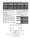
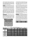
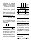
TOUCH PILOT MACHINE CONTROL — Machine On/Off
control is determined locally by pushing the Start/Stop button
on the Touch Pilot display. Pressing this button will cause the
Equipment Start screen to be displayed. See Fig. 15.
Fig. 15 — Equipment Start Screen