


36
To configure this option with the Touch Pilot™ display:
To configure this option with the Navigator™ display:
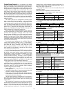
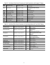
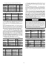
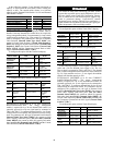
In the example in Fig. 21 using Return Water Temperature
Reset, the chilled water temperature will be reset by 5° F
(2.8° C) when the Fluid Temperature Difference is 2° F
(1.1° C) and 0° F (0° C) reset when the Temperature Difference
is 10° F.
SPACE TEMPERATURE RESET — The control system is
also capable of temperature reset based on space temperature
(SPT). An accessory sensor must be used for SPT reset
(33ZCT55SPT). The Energy Management Module (EMM) is
also required for temperature reset using space temperature.
To use Space Temperature Reset, four variables must be
configured. Cooling Reset Type (Cooling Reset Select, CRST)
must be enabled. The space temperature at which no tempera-
ture reset is required, Space T No Reset Temp (Space T No
Reset Value, CRS1) must be set. The space temperature at
which full temperature reset is required, Space T Full Reset
Temp (Space T Full Reset Value, CRS2) must be set. Finally,
the amount of temperature reset desired, Degrees Cool Reset
(Cooling Reset Deg. Value, DRGC), must be set.
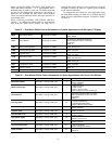
To configure this option with the Touch Pilot display:
To configure this option with the Navigator display:
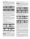
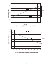
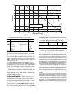
In the space temperature reset example in Fig. 22, 0° F
(0° C) chilled water set point reset at 72 F (22.2 C) space
temperature and 6° F (3.3° C) reset at 68 F (20.0 C) space
temperature.
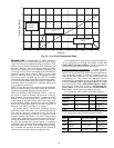
4-20 mA TEMPERATURE RESET — The control system is
also capable of temperature reset based on an externally pow-
ered 4 to 20 mA signal. The Energy Management Module
(EMM) is required for temperature reset using a 4 to 20 mA
signal.
To use 4-20 mA Temperature Reset, four variables must be
configured. Cooling Reset Type (Cooling Reset Select, CRST)
must be enabled. The milliamp signal at which no temperature
reset is required, Current No Reset Value (Current No Reset
Value, CRV1), must be set. The milliamp signal at which full
temperature reset is required, Current Full Reset Value (Cur-
rent Full Reset Value, CRV2), must be set. Finally, the
amount of temperature reset desired, Degrees Cool Reset
(Cooling Reset Deg. Value, DRGC), must be set.
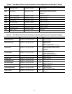
To configure this option with the Touch Pilot™ display:
To configure this option with the Navigator™ display:
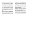
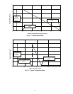
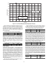
In the example in Fig. 23, at 4 mA no reset takes place and
at 20 mA, 5° F (2.8° C) chilled water set point reset is required.
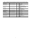
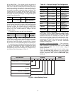
DISPLAY NAME PATH LINE NO. VALUE
Cooling Reset
Select
Main
Menu Config USER
19
Default =0
(No Reset)
2 (Delta T)
Delta T No
Reset Temp
Main
Menu Setpoint SETPOINT
7
Default =
0 F (0 C)
Delta T Full
Reset Temp
Main
Menu Setpoint SETPOINT
8
Default =
0 F (0 C)
Cooling Reset
Deg. Value
Main
Menu Setpoint SETPOINT
13
Default =
0 F (0 C)
ITEM ITEM EXPANSION PATH VALUE
CRST
Cooling Reset
Type
Configuration RSET
Default =
No Reset
Delta T Temp
CRT1
Delta T No
Reset Temp
Setpoints COOL
Default =
0 F (0 C)
CRT2
Delta T Full
Reset Temp
Setpoints COOL
Default =
0 F (0 C)
DGRC
Degrees Cool
Reset
Setpoints COOL
Default =
0 F (0 C)
DISPLAY NAME PATH
LINE
NO.
VALUE
Cooling Reset
Select
Main Menu
Config USER
19
Default =0
(No Reset)
4 (Space Temp)
Space T No
Reset Value
Main Menu
Setpoint SETPOINT
11
Default =
14 F (–10 C)
Space T Full
Reset Value
Main Menu
Setpoint SETPOINT
12
Default =
14 F (–10 C)
Cooling Reset
Deg. Value
Main Menu
Setpoint SETPOINT
13
Default =
0 F (0 C)
ITEM ITEM EXPANSION PATH VALUE
CRST Cooling Reset Type Configuration RSET
Default =
No Reset
Space Temp
CRS1
Space T No Reset
Te mp
Setpoints COOL
Default =
14 F (–10 C)
CRS2
Space T Full Reset
Te mp
Setpoints COOL
Default =
14 F (–10 C)
DGRC Degrees Cool Reset Setpoints COOL
Default =
0 F (0 C)
CAUTION
Care should be taken when interfacing with other control
systems due to possible power supply differences such as a
full wave bridge versus a half wave rectification. Connec-
tion of control devices with different power supplies may
result in permanent damage. The ComfortLink™ controls
incorporate power supplies with half wave rectification. A
signal isolation device should be utilized if the signal gen-
erator incorporates a full wave bridge rectifier.
DISPLAY NAME PATH LINE NO. VALUE
Cooling Reset
Select
Main Menu
Config USER
19
Default =0
(No Reset)
3 (4-20mA
Control)
Current No
Reset Value
Main Menu
Setpoint SETPOINT
9 Default = 0.0
Current Full
Reset Value
Main Menu
Setpoint SETPOINT
10 Default = 0.0
Cooling Reset
Deg. Value
Main Menu
Setpoint SETPOINT
13
Default =
0.0 F (0.0 C)
ITEM ITEM EXPANSION PATH VALUE
CRST
Cooling Reset
Type
Configuration RSET
Default =
No Reset
4-20mA Input
CRV1
Current No
Reset Temp
Setpoints COOL Default = 0.0
CRV2
Current Full
Reset Temp
Setpoints COOL Default = 0.0
DGRC
Degrees Cool
Reset
Setpoints COOL Default = 0.0