


28
Cooler Pump Control — It is required for all chillers
that the cooler pump control be utilized unless the chilled water
pump runs continuously or the chilled water system contains a
suitable concentration of antifreeze solution. When the Cooler
Pumps Sequence is configured, the cooler pump output will be
energized when the chiller enters an "ON" mode. The cooler
pump output is also energized when certain alarms are generat-
ed. The cooler pump output should be used as an override to
the external pump control if cooler pump control is not utilized.
The cooler pump output is energized if a P.01 Water Exchanger
Freeze Protection alarm is generated, which provides addition-
al freeze protection if the system is not protected with a suitable
antifreeze solution.
The 30XW units can be configured for external cooler
pump control. Cooler Pumps Sequence is the variable that
must be confirmed in the field. Proper configuration of the
cooler pump control is required to provide reliable chiller oper-
ation. The factory default setting for Cooler Pumps Sequence is
0 (No Pump). The configuration settings for Cooler Pumps Se-
quence are 1 (1 pump only) for single pump control and 2 (2
pumps auto). Configuration settings 3 (PMP 1 Manual) and 4
(PMP 2 Manual) are for dual pump control only.
If the Cooler Pumps Sequence (PUMP) is set to 1, the con-
trol will start the pump. If a flow failure is detected, the unit
will shut down and must be manually reset. If the Cooler
Pumps Sequence (PUMP) is set to 2, the control will start the
lead pump and automatically alternate the operation of the
pumps to even the wear. If a flow failure is detected, the unit
will shut down and the lag pump will attempt to start. If flow is
established within the Unit Off to On Delay (DELY) period the
unit will restart automatically.
Two manual control options are also available. When the
Cooler Pumps Sequence (PUMP) is set to 3, Cooler Pump 1
will always operate. If a flow failure is detected, the unit will
shut down and must be manually reset. When the Cooler
Pumps Sequence (PUMP) is set to 4, Cooler Pump 2 will al-
ways operate. If a flow failure is detected, the unit will shut
down and must be manually reset.
For all Cooler Pumps Sequence (PUMP) settings (including
0), closure of both the chilled water flow switch (CWFS) and
the chilled water pump interlock contact (connected across
TB5 terminals 1 and 2) are required. In addition, for Cooler
Pumps Sequence settings of PUMP = 1, 2, 3, 4, normally open
auxiliary contacts for Pump 1 and Pump 2 (wired in parallel)
must be connected to the violet and pink wires located in the
harness from the MBB-J5C-CH18 connector. The wires in the
harness are marked "PMP1-13" and "PMP1-14". See the field
wiring diagram in the 30XW Installation Instructions.
Regardless of the cooler pump control option selected, if the
chilled water flow switch/interlock does not close within the
Unit Off to On Delay period after the unit is enabled and in an
ON mode, alarm P.91 will be generated. Other conditions
which will trigger this alarm include:
• Cooler pump interlock is open for at least 15 seconds during
chiller operation.
• Lag chiller in Master/Slave Control pump interlock does not
close after 1 minute of the pump start command.
• Cooler pump control is enabled and the chilled water flow
switch/interlock is closed for more than 2 minutes following
a command to shut down the pump.
The last alarm criterion can be disabled. If Flow Checked if
Pmp Off (Configuration OPTN P.LOC) is set to NO, the con-
trol will ignore the pump interlock input if the cooler pump
output is OFF.
The ComfortLink™ controls have the ability to periodically
start the pumps to maintain the bearing lubrication and seal in-
tegrity. If Pump Sticking Protection (Configuration OPTN
PM.PS) is set to YES, and if the unit is off at 2:00 PM, a pump
will be started once each day for 2 seconds. If the unit has
2 pumps, Pump 1 will be started on even days (such as day 2, 4,
or 6 of the month); Pump 2 will be started on odd days. The de-
fault for this option is PM.PS=NO.
The pump will continue to run for 60 seconds after an off
command is issued.
COOLER PUMP CONTROL CONFIGURATIONS
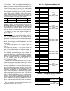
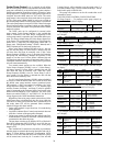
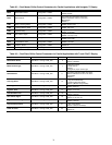
No Pump Control
— To configure cooler pump control op-
tions with the Touch Pilot™ display:
To configure cooler pump control options with the Naviga-
tor™ display:
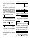
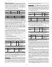
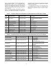
Single Pump Control
— To configure cooler pump control
options with the Touch Pilot display:
To configure cooler pump control options with the Naviga-
tor display:
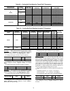
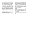
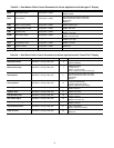
Dual Pump and Manual Control
— To configure cooler
pump control options with the Touch Pilot™ display:
To configure cooler pump control options with the Naviga-
tor™ display:
DISPLAY NAME PATH
LINE
NO.
VALUE
Cooler Pumps
Sequence
Main
Menu Config USER
8
0 (No Pump
Control)
ITEM ITEM EXPANSION PATH VALUE
PUMP
Cooler Pumps
Sequence
Configuration OPTN No Pump
DISPLAY NAME PATH
LINE
NO.
VALUE
Cooler Pumps
Sequence
Main
Menu Config USER
8
1 (Single
Pump Control)
Pump Sticking
Protection
Main
Menu Config USER
15
Default = No
No = Disabled
Yes = Enabled
Flow Checked
if C Pump Off
Main
Menu Config USER
17
Default = Yes
No = Disabled
Yes = Enabled
ITEM ITEM EXPANSION PATH VALUE
PUMP
Cooler Pumps
Sequence
Configuration OPTN 1 Pump Only
PM.PS
Periodic Pump
Start
Configuration OPTN
Default = No
No = Disabled
Yes = Enabled
P.LOC
Flow Checked
if Pmp Off
Configuration OPTN
Default = Yes
No = Disabled
Yes = Enabled
DISPLAY NAME PATH
LINE
NO.
VALUE
Cooler Pumps
Sequence
Main Menu
Config USER
8
2 (2 Pumps Automatic)
3 (Pump 1 Manual)
4 (Pump 2 Manual)
Pump Auto
Rotation Delay
Main Menu
Config USER
14 Default = 48 hours
Pump Sticking
Protection
Main Menu
Config USER
15
Default = No
No = Disabled
Yes = Enabled
Flow Checked
if C Pump Off
Main Menu
Config USER
17
Default = Yes
No = Disabled
Yes = Enabled
ITEM ITEM EXPANSION PATH VALUE
PUMP
Cooler Pumps
Sequence
Configuration OPTN
2 Pumps Auto
PMP1 Manual
PMP2 Manual
ROT.P
Pump Rotation
Delay
Configuration OPTN
Default =
48 hours
PM.PS
Periodic Pump
Start
Configuration OPTN
Default = No
No = Disabled
Yes = Enabled
P.LOC
Flow Checked
if Pmp Off
Configuration OPTN
Default = Yes
No = Disabled
Yes = Enabled