


66
INSPECTING/CLEANING HEAT EXCHANGERS — In-
spect and clean cooler tubes at the end of the first operating
season. Because these tubes have internal ridges, a rotary-type
tube cleaning system is necessary to fully clean the tubes. Tube
condition in the cooler will determine the scheduled frequency
for cleaning, and will indicate whether water treatment is
adequate in the chilled water/brine circuit. Inspect the entering
and leaving water thermistor wells for signs of corrosion or
scale. Replace the well if corroded or remove any scale if
found.
WATER TREATMENT — Untreated or improperly treated
water may result in corrosion, scaling, erosion or algae. The
services of a qualified water treatment specialist should be
obtained to develop and monitor a treatment program.
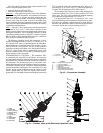
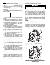
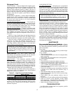
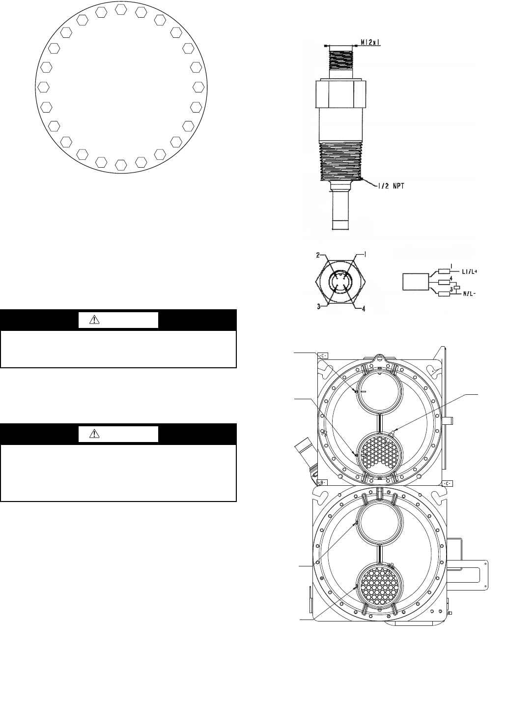
CHILLED WATER FLOW SWITCH — A factory-installed
flow switch is installed in the entering water nozzle for all ma-
chines. See Fig. 50 and 51. This is a thermal-dispersion flow
switch. Figure 50 shows typical installation. If nuisance trips of
the sensor are occurring, follow the steps below to correct:
When power is supplied to the device, a warm-up period is
initiated. The warm-up period may take up to 30 seconds.
When enough flow is detected, the switch contacts will close.
The switch closure does not indicate minimum flow require-
ments have been met for the machine.
1. Check to confirm that all strainers are clean, valves are
open and pumps are running. For the case of variable
frequency drive (VFD) controlled pumps, ensure the
minimum speed setting has not been changed.
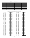
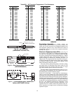
2. Measure the pressure drop across the cooler (evaporator).
Use the cooler pressure drop curves in Fig. 27-37 to cal-
culate the flow and compare this to system requirements.
3. If the contacts do not close with sufficient flow, then
check the wiring connection to the MBB. If the input sig-
nal is not closed, then the switch needs to be replaced.
CAUTION
Hard scale may require chemical treatment for its preven-
tion or removal. Consult a water treatment specialist for
proper treatment procedures.
CAUTION
Water must be within design flow limits, clean and treated
to ensure proper machine performance and reduce the
potential of tubing damage due to corrosion, scaling, and
algae. Carrier assumes no responsibility for cooler damage
resulting from untreated or improperly treated water.
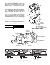
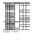
Fig. 51 — Flow Switch (Typical)
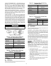
LEGEND
CEWT — Condenser Entering Water Thermistor
CLWT — Condenser Leaving Water Thermistor
CWFS — Chilled Water Flow Switch
EWT — Entering Water Thermistor
LWT — Leaving Water Thermistor
OUT
OUT
IN
IN
LWT
EWT
CLWT
CWFS
CEWT
A30-4846
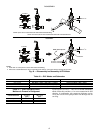
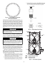
Fig. 49 — Cooler Head Recommended
Bolt Torque Sequence
1
20
8
6
19
16
15
3
23
10
12
24
14
13
17
5
7
18
2
4
21
9
11
22
A30-4845
Fig. 50 — Chilled Water Flow Switch
WIRING
a30-4708