


131
APPENDIX C — CCN TABLES (cont)
SERVICE CONFIGURATION TABLES (cont)
*Not supported.
*Not supported. Must be configured at default.
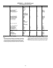
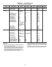
NOTE: This table shall be downloadable at any time. However, modified value shall not be used by tasks until the unit is in OFF state. This shall not apply to the Varifan
gains that shall be modified at any time and used immediately by the head pressure control tasks even if the unit is in operation.
*Not supported.
NOTE: This table shall be used for purposes of transplanting the devices on time in the event of a module hardware failure or software upgrade via downloading. It shall
be usable only if all items are still null. Afterwards, its access shall be denied.
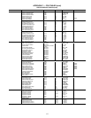
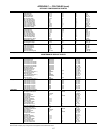
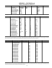
TABLE DISPLAY NAME RANGE DEFAULT UNITS POINT NAME WRITE STATUS
MAINTCFG MAINTENANCE CONFIG
Servicing Alert Enable/Disable Disable s_alert
Refrigerant Charge Ctrl Enable/Disable Disable charge_c
Water Loop Control Enable/Disable Disable wloop_c
CPump 1 Ctl Delay (days) 0-1000 0 cpump1_c
CPump 2 Ctl Delay (days) 0-1000 0 cpump2_c
HPump 1 Ctrl Delay (days)* 0-1000 0 hpump1_c
HPump 2 Ctrl Delay (days)* 0-1000 0 hpump2_c
Water Filter Ctrl (days) 0-1000 0 wfilte_c
Oil Filter A Ctrl (days) 0 to 1000 0 oilfia_c
Oil Filter B Ctrl (days) 0 to 1000 0 oilfib_c
Oil Filter C Ctrl (days) 0 to 1000 0 oilfic_c
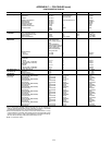
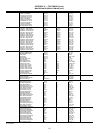
TABLE DISPLAY NAME RANGE DEFAULT UNITS POINT NAME WRITE STATUS
SERVICE1 Cooler Fluid Type 1/2
1=Water
2=Brine
1 flui_typ
Flow Switch SP* 0-60 1 flow_sp
Brine Freeze Setpoint –20.0-34.0 34 °F freezesp
Brine Minimum Fluid Temp 10.0-34.0 38 °F mini_lwt
Condenser Fluid Type 1/2
1=Water
2=Brine
1 cond_typ
Entering Fluid Control Yes/No No ewt_opt
Prop PID Gain Varifan –20.0-20.0 2.0 hd_pg
Int PID Gain Varifan –5.0-5.0 0.2 hd_ig
Deri PID Gain Varifan –20.0-20.0 0.4 hd_dg
Maximum Ducted Fan Speed 20-100 100 % fan_max
EXV A Superheat Setpoint 12.6-44 14.4 ^F sh_sp_a
EXV B Superheat Setpoint 12.6-44 14.4 ^F sh_sp_b
EXV C Superheat Setpoint 12.6-44 14.4 ^F sh_sp_c
Pinch offset circuit A –3.0-3.0 0 ^F p_ofst_a
Pinch offset circuit B –3.0-3.0 0 ^F p_ofst_b
Pinch offset circuit C –3.0-3.0 –3.6 ^F p_ofst_c
EXV MOP Setpoint 40-55 62 °F mop_sp
High Pressure Threshold 200-290 275.5 psi hp_th
Cooler Heater Delta Spt 1-6 2 ^F heatersp
Auto Start When SM Lost Enable/Disable Disable auto_sm
3way Valve Min Position 0-50 0 % min_3w
3way Valve Max Position 20-100 100 % max_3w
Economizer SH Setpoint A 5-15 10.8 ^F esh_sp_a
Economizer SH Setpoint B 5-15 10.8 ^F esh_sp_b
Economizer SH Setpoint C 5-15 10.8 ^F esh_sp_c
Fast Loading Sequence 0-4 0 fastload
EWT Probe on Cir A Side Yes/No Yes ewt_cirA
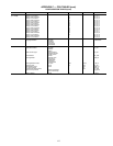
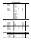
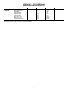
TABLE DISPLAY NAME RANGE UNITS POINT NAME WRITE STATUS
TABLE TO BE USED FOR RUN TIMES UPDATE IN CASE OF CONTROL RETROFIT
UPDHRFAN*
Free Cooling A Pump Hours 0 hours hr_fcp_a
Free Cooling B Pump Hours 0 hours hr_fcp_b
Circuit A Defrost Number 0 nb_def_a
Circuit B Defrost Number 0 nb_def_b
Circuit A Fan #1 Hours 0 hours hr_fana1
Circuit A Fan #2 Hours 0 hours hr_fana2
Circuit A Fan #3 Hours 0 hours hr_fana3
Circuit A Fan #4 Hours 0 hours hr_fana4
Circuit A Fan #5 Hours 0 hours hr_fana5
Circuit A Fan #6 Hours 0 hours hr_fana6
Circuit A Fan #7 Hours 0 hours hr_fana7
Circuit A Fan #8 Hours 0 hours hr_fana8
Circuit A Fan #9 Hours 0 hours hr_fana9
Circuit A Fan #10 Hours 0 hours hrfana10
Circuit B Fan #1 Hours 0 hours hr_fanb1
Circuit B Fan #2 Hours 0 hours hr_fanb2
Circuit B Fan #3 Hours 0 hours hr_fanb3
Circuit B Fan #4 Hours 0 hours hr_fanb4
Circuit B Fan #5 Hours 0 hours hr_fanb5
Circuit B Fan #6 Hours 0 hours hr_fanb6
Circuit B Fan #7 Hours 0 hours hr_fanb7
Circuit B Fan #8 Hours 0 hours hr_fanb8
Circuit B Fan #9 Hours 0 hours hr_fanb9
Circuit B Fan #10 Hours 0 hours hrfanb10
Circuit C Fan #1 Hours 0 hours hr_fanc1
Circuit C Fan #2 Hours 0 hours hr_fanc2
Circuit C Fan #3 Hours 0 hours hr_fanc3
Circuit C Fan #4 Hours 0 hours hr_fanc4
Circuit C Fan #5 Hours 0 hours hr_fanc5
Circuit C Fan #6 Hours 0 hours hr_fanc6
Circuit C Fan #7 Hours 0 hours hr_fanc7
Circuit C Fan #8 Hours 0 hours hr_fanc8