


15
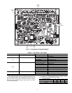
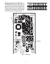
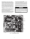
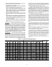
MLV/Condenser Board — One auxiliary board is op-
tionally installed in each unit. See Fig. 11. The auxiliary board
contains an analog output for head pressure control and dis-
crete outputs for minimum load control. The auxiliary board
responds to commands from the MBB and sends the MBB the
results of the channels it monitors via the Local Equipment
Network (LEN). See below for auxiliary board A, B and C DIP
switch addresses. See Table 8 for inputs and outputs.
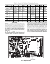
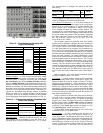
Table 8 — Auxiliary Board Outputs
AUX BOARD
DIP SWITCH
123 45678
Address: OFF ON OFF OFF ON OFF ON OFF
DESCRIPTION INPUT/OUTPUT I/O TYPE DISPLAY MODULE POINT NAME
CONNECTION POINT
Pin Notation
Power (24 vac supply) —— —
AUX-J1
11 24 vac
12 Ground
Local Equipment Network —— —
AUX-J9
+ RS485 Port (D+)
G RS485 Port (Gnd)
-RS485 Port (D-)
+ RS485 Port (D+)
G RS485 Port (Gnd)
-RS485 Port (D-)
Condenser Head Pressure Control
Speed Signal
HD_A 0-10 VDC Head Press Actuator Pos, SPD.A
AUX-CH9
+ Signal
- Ground
Minimum Load Valve A MLV-A Solenoid Minimum Load Valve Circuit A, MLV.A AUX-J2-CH3
Minimum Load Valve B MLV-B Solenoid Minimum Load Valve Circuit B, MLV.B AUX-J2-CH4
1
2
3
4
5
6
7
8
ON
100K
100K
100K
CH1
CH2 CH3
CH4 CH5 CH6 CH7 CH8
TR1 TR2 TR3 TR4 TR5 TR6 TR7 TR8
STAT US SIO (LEN)
LOCATION OF
SERIAL NUMBER
24 VAC
CH13 CH14
J9
J1
CH9
CH10
CH11
CH12
JP2
C61
CH13
D12
JP1
L3
L5
U21
L2
D6
D5
Q5
Y1
D7
D8
S1
D3
U1
Q1
U5
U6
U7
U8
U9
Q10
Q11
U10
J4
J3
J2
U4
U2
Q12
Q60
3 2 1
– G +
3 2 1
– G +
DIP SWITCH
Fig. 11 — Auxiliary Board with Optional Minimum Load Control or Head Pressure Control
a30-4046