77
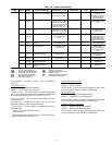
• a liquid line refrigerant restriction, filter drier, service valve,
etc.
• refrigerant charge
Low Suction Superheat
Alarm 77 — Circuit A (P.11)
Alarm 78 — Circuit B (P.12)
Criteria for Trip — The criteria are tested when the circuit is
ON. This alarm is generated if the following criterion is met:
The EXV position is equal to or less than 5% and the cir-
cuit’s Suction Superheat (Suction Gas Temperature – Saturated
Suction Temperature) is less than the Suction Superheat Set
Point (EXVA Superheat Setpoint, SHP.A, EXVB Superheat
Setpoint, SHP.B, or EXVC Superheat Setpoint, SHP.C) by at
least 5° F (2.8° C) or the circuit Saturated Suction Temperature
is greater than Maximum Operating Pressure (MOP) set point
(EXV MOP Setpoint, MOP) for more than 5 minutes.
Action to be Taken — The circuit is shut down normally.
Reset Method — Automatic, first occurrence in 24 hours.
Manual, if more than one occurrence in 24 hours.
Possible Causes — If this condition is encountered, check the
following items:
• suction pressure transducer wiring to Main Base Board
• board for a faulty channel
• faulty suction transducer
• suction gas thermistor wiring to EXV Board 1 or to EXV
Board 2
• suction gas thermistor sensor for accuracy
• EXV Board 1 or EXV Board 2 faulty channel
• EXV operation
• confirm maximum operating pressure set point
• refrigerant charge level
Alarm 80 — Interlock Failure (P.14)
Criteria for Trip — The criteria are tested whether the unit is
ON or OFF. This alarm is generated if the lockout switch
(located in the Energy Management Module) is closed during
normal operation.
Action to be Taken — All compressors are shut down immedi-
ately without going through pumpdown. and is not allowed to
start.
Reset Method — Automatic, first occurrence in 24 hours.
Manual, if more than one occurrence in 24 hours.
Possible Causes — If this condition is encountered, check the
following items:
• chilled water flow switch operation
• water flow. Be sure all water isolation valves are open and
check water strainer for a restriction
• interlock wiring circuit
• power supply to the pump
• control signal to the pump controller
• chilled water pump operation
• cooler pump contactor for proper operation
Alarm 81 — Electrical Box Thermostat Failure/Reverse
Rotation (P.28)
Criteria for Trip — The alarm criteria are checked whether the
unit is ON or OFF. If channel 15A on the MBB, which is used
for field wired external pump interlock, is open then the alarm
will be generated.
Action to be Taken — Unit shut down or note allowed to start.
Reset Method — Automatic, if the channel is closed, the unit
will start normally.
Possible Causes — If this condition is encountered, check the
following items:
• jumper wiring on TB5-1 and TB5-2 when channel is not in
use
• external pump interlock open
• field wiring for the external pump interlock open
Alarm 82 — Loss of Communication with System Manager
(P.29)
Criteria for Trip — The criterion is tested whether the unit is
ON or OFF. This alarm is generated if the System Manager
had established communications with the machine and is then
lost for more than 2 minutes.
Action to be Taken — The action to be taken by the control
depends on the configuration. If Auto Start when SM lost is
enabled, (Cooler Heater Delta Spt, AU.SM=YES), then the
unit will force the CCN Chiller Start Stop to ENBL and clear
all forced points from the System Manager. The unit will revert
to stand-alone operation.
Reset Method — Automatic, once communication is
re-established.
Possible Causes — If this condition is encountered, check the
following items:
• communication wiring
• power supply to the System Manager and unit controls
Alarm 83 — Master/Slave Communication Failure (P.30)
Criteria for Trip — The criterion is tested whether the units are
ON or OFF and a master and slave machine has been config-
ured, (Master/Slave Select, MSSL=1 and Master/Slave
Select, MSSL=2). If communication is lost for more than 3
minutes, this alarm is generated.
Action to be Taken — Dual chiller control will be disabled and
each unit will operate in Stand-Alone mode.
Reset Method — Automatic, once communication is
re-established.
Possible Causes — If this condition is encountered, check the
following items:
• CCN wiring
• control power to each Main Base Board, master and slave
• confirm correct configuration
Low Oil Pressure
Alarm 84 — Circuit A (P.67)
Alarm 85 — Circuit B (P.68)
Criteria for Trip — The criteria are tested only when the com-
pressor is ON. The alarm is generated if one of the following
occurs, where:
oil = oil pressure transducer reading for the appropriate com-
pressor
sp = suction pressure reading for the affected circuit
dp = discharge pressure reading for the affected circuit
oil_sp1 = 0.7 x (dp-sp) + sp
oil_sp2 = sp + 7.2 psi (15 seconds after start)
oil_sp2 = sp + 14.5 psi (45 seconds after start)
• If the compressor starts with the ambient temperature
(OAT less than 36° F [2° C] the oil pressure monitoring
is delayed by 30 seconds.
Action to be Taken — The affected compressor will be
stopped. The other compressors will continue to operate.
Reset Method — Manual.
Possible Causes — If this condition is encountered, check the
following items:
• sensor wiring to the CPM Board
• board for a faulty channel
• faulty transducer
• plugged oil filter
• faulty oil solenoid valve coil
• stuck oil solenoid valve
• stuck check valve
• manual shut off valve to ensure it is not fully open
• confirm unit configuration


