


9
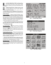
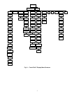
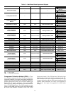
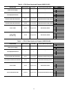
Table 2 — ComfortLink™ Navigator™ Display Menu Structure
CONTROLS
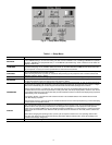
General —
The 30XW water-cooled liquid chillers contain
the ComfortLink™ electronic control system that controls and
monitors all operations of the chiller. The control system is
composed of several components as listed in the following sec-
tions. All machines have a Main Base Board (MBB), Touch Pi-
lot™ module or Navigator™ device, electronic expansion
valve board (EXV), auxiliary board, Compressor Protection
board, Emergency On/Off switch, and an Enable-Off-Remote
Contact switch.
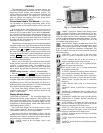
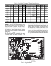
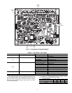
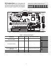
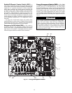
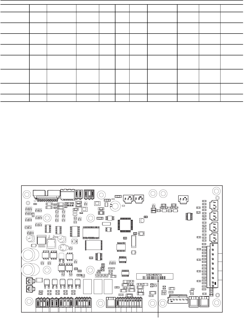
Main Base Board (MBB) — The MBB is the core of
the ComfortLink control system. It contains the major portion
of operating software and controls the operation of the
machine. See Fig. 8. The MBB continuously monitors input/
output channel information received from its inputs and from
all other modules. The MBB receives inputs from status and
feedback switches, pressure transducers and thermistors. The
MBB also controls several outputs. Some inputs and outputs
that control the chiller are located on other boards, but are
transmitted to or from the MBB via the internal communica-
tions bus. Information is transmitted between modules via a
3-wire communication bus or LEN (Local Equipment Net-
work). The CCN (Carrier Comfort Network
®
) bus is also sup-
ported. Connections to both LEN and CCN buses are made at
TB3. For a complete description of Main Base Board inputs
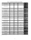
and outputs and their channel identifications, see Table 3.
MODE
RUN
STATUS
SERVICE
TEST
TEMPERATURES PRESSURES
SET
POINTS
INPUTS OUTPUTS CONFIGURATION
TIME
CLOCK
OPERATING
MODES
ALARMS
Auto Display
(VIEW)
Manual
Test Mode
(TEST)
Unit
Temperatures
(UNIT)
Circuit A
Pressures
(PRC.A)
Cooling
Setpoints
(COOL)
General
Inputs
(GEN.I)
Circuit A
Outputs
(CIR.A)
Display
Configuration
(DISP)
Time of Day
(TIME)
Operating
Control Type
(SLCT)
Reset Current
Alarms
(R.ALM)
Machine
Starts/Hours
(RUN)
Quick
Test Mode
(QUIC)
Circuit A
Temperatures
(CIR.A)
Circuit B
Pressures
(PRC.B)
Heating
Setpoints
(HEAT)
Circuit B
Outputs
(CIR.B)
Unit
Configuration
(UNIT)
Day, Date
(DATE)
Operating
Modes
(MODE)
Current
Alarms
(ALRM)
Compressor
Run Hours
(HOUR)
Circuit B
Temperatures
(CIR.B)
Circuit C
Pressures
(PRC.C)
Misc.
Setpoints
(MISC)
Circuit C
Outputs
(CIR.C)
Service
Configurations
(SERV)
Schedule 1
(SCH1)
Alarm
History
(H.ALM)
Compressor
Starts
(STRT)
Circuit C
Temperatures
(CIR.C)
General
Outputs
(GEN.O)
Options
Configuration
(OPTN)
Schedule 2
(SCH2)
Fan Run
Hours
(FAN)
Reset,
Demand Limit,
Master/Slave
(RSET)
Holidays
(HOLI)
Compressor
Disable
(CP.UN)
Service
Maintenance
Configuration
(MCFG)
Predictive
Maintenance
(MAIN)
Software Versions
(VERS)
221
221
221
221
195
195
195
195
195
195
195
CH1 CH2 CH3
CH4
CH11 CH12
LOCATION OF
SERIAL NUMBER
CH13
CH14
CH
15A
J4
ANALOG
INPUTS
J3
J2C
J2B
24 VAC
J1A
+ G –
DISCRETE
INPUTS
J5A
CH
15a
11
C16
J2A
TR1 TR2 TR3 TR4 TR5
CH19 CH20 CH21 CH22 CH23 CH24 CH25 CH26
J8
CH17
CH18
J5B
J5C
THERMISERS PRESSURES
CH5
CH6 CH7 CH8
CH9
J7A J7B
J7C
J7D
RELAY
OUTPUTS
MOV1
C41
C42 C43
C32
C33
C34
C35
12/11
12/11
J10
LEN
+ G -
STATUS
J9A
K1
K2
D15
J6
CCN
CH10
+ G –
SIO
(LEN)
J9C
J9B
+ G –
LEN
LEN
CCN J13 J9D
+
C
+
C
CH
16a
+
C
CH
16b
Fig. 8 — Main Base Board
a30-4255