


61
EXV TROUBLESHOOTING PROCEDURE — There are
two different economizer EXVs. Both of the economizer
EXVs have a total of 2785 steps. There are three different main
EXVs, which all have a total of 4260 steps. The EXV motor
moves at 150 steps per second. Commanding the valve to
either 0% or 100% will add an additional 160 steps to the
move, to ensure the valve is open or closed completely.
Follow the steps below to diagnose and correct EXV
problems. Check EXV motor operation first. Switch the
Enable/Off/Remote (EOR) Contact switch to the Off position.
Check the appropriate circuit EXV, Circuit A EXV % Open
(Circuit A EXV Position, EXV.A) or Circuit B EXV % Open
(Circuit B EXV Position, EXV.B). The current value of 0 will
be displayed. Increase the EXV position to select 100% valve
position. The actuator should be felt moving through the EXV.
To close the valve, select 0%. The actuator should knock when
it reaches the bottom of its stroke. See Table 40 for a list of
EXV modes and submodes.
If the valve is not working properly, continue with the fol-
lowing test procedure:
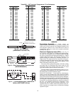
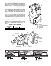
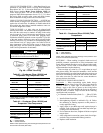
Check the 8-position DIP switch on the board for the proper
address (Fig. 10). Check the EXV output signals at appropriate
terminals on the EXV module. For 30XW150,325 units, con-
nect the positive test lead to EXV-J2A terminal 5 for Circuit A
and to EXV-J2B terminal 5 for Circuit B.
For 30XW175,200,350,400 units connect positive test lead
to EXV(X)-J2A terminal 5 for EXV(X) and EXV(X)-J2B ter-
minal 5 for Economizer EXV(X). Using the Service Test pro-
cedure on page 83, move the valve output under test to 100%.
DO NOT short meter leads together or pin 5 to any other pin,
as board damage will occur. During the next several seconds,
carefully connect the negative test lead to pins 1,2,3 and 4 in
succession. Digital voltmeters will average this signal and
display approximately 6 vdc. If the output remains at a constant
voltage other than 6 vdc or shows 0 volts, remove the connec-
tor to the valve and recheck.
Select 0% to close the valve.
NOTE: When the valve is stationary, the output from the EXV
board is 12-vdc.
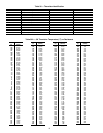
See Tables 6 and 7. If a problem still exists, replace the
EXV board. If the reading is correct, the expansion valve and
EXV wiring should be checked. Check the EXV connector and
interconnecting wiring.
1. Check color-coding and wire connections. Make sure
they are connected to the correct terminals at the EXV
board and EXV plug and that the cables are not crossed.
2. Check for continuity and tight connection at all pin
terminals.
Check the resistance of the EXV motor windings. For
30XW150,325 units remove the EXV module plug EXV-J2A
for Circuit A EXV and EXV-J2B for Circuit B EXV. For
30XW175,200,350,400 units remove the EXV module plug
EXV(X)-J2A for main EXV and EXV(X)-J2B for economizer
EXV. Check the resistance of the two windings between pins 1
and 3 for one winding and pins 2 and 4 for the other winding.
The resistance should be 52 ohms (± 5.2 ohms). Also check
pins 1-4 for any shorts to ground.
Inspecting/Opening Electronic Expansion Valves
To check the physical operation of an EXV, the following
steps must be performed.
1. Close the liquid line service valve of the circuit to be
checked. Put the Enable/Off/Remote Contact (EOR)
switch in the Off position. Enter the Service Test mode
and change Service Test Enable, T.REQ from OFF to
ON. A password may be required. Switch the EOR
switch to the Enable position. Under the COMP sub-
mode, enable one of the compressors (CP.xn) for the cir-
cuit. Let compressor run until gage on suction pressure
port reads 10 psig (68.9 kPa). Turn the compressor off.
The compressor will turn off. Immediately after the com-
pressor shuts off, manually close the actuated ball valve
(ABV). If the unit is equipped with suction service valves
and economizer service valves, close both valves. Clos-
ing the valves will minimize the amount of charge that
will have to be removed from the system after pump
down.
2. Remove any remaining refrigerant from the system low
side using proper recovering techniques. The economizer
assembly has a
1
/
4
-in. access connection which can be
used to remove charge from the inlet of the EXVs. Turn
off the line voltage power supply to the compressors.
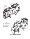
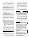
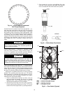
3. The expansion valve motor is hermetically sealed inside
the top portion of the valve. See Fig. 43. Disconnect the
EXV plug. Carefully unscrew the motor portion from the
body of the valve. The EXV operator will come out with
the motor portion of the device. Reconnect the EXV plug.
4. Enter the appropriate EXV test step under the (QUIC)
Service Test mode Locate the desired item Circuit A
EXV Position, EXV.A or Circuit B EXV Position,
EXV.B. Change the position to 100%. Observe the opera-
tion of the lead screw. See Fig. 43. The motor should be
turning, raising the operator closer to the motor. Motor
actuator movement should be smooth and uniform from
fully closed to fully open position. Select 0% and check
open to closed operation. If the valve is properly connect-
ed to the processor and receiving correct signals, yet does
not operate as described above, the sealed motor portion
of the valve should be replaced.
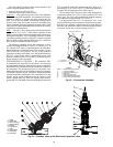
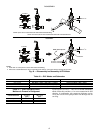
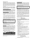
Installing EXV Motor
If re-installing the motor, be sure to use a new gasket in the
assembly. See Fig. 44. It is easier to install the motor assembly
with the piston in the fully closed position. Insert the motor into
the body of the EXV. Tighten the motor to the body to 36 ft-lb
(50 N-m) and then tighten the valve another 30 degrees.
Moisture Liquid Indicator — Clear flow of liquid refrigerant
indicates sufficient charge in system. Bubbles in the sight glass
indicate undercharged system or presence of noncondensables.
Moisture in system, measured in parts per million (ppm),
changes color of indicator. See Table 41. Change filter drier at
first sign of moisture in system.
Filter Drier — Whenever moisture-liquid indicator shows
presence of moisture, replace filter drier(s). There is one filter
drier assembly on each circuit with two cores. Refer to the Car-
rier Standard Service Techniques Manual, Chapter 1, Refriger-
ants, for details on servicing filter driers.
IMPORTANT: Obtain replacement gaskets before
opening EXV. Do not re-use gaskets.
CAUTION
Ensure refrigerant is removed from both the inlet and outlet
of EXV assemblies. Equipment damage could result.
IMPORTANT: Obtain replacement gasket before
opening EXV. Do not re-use gaskets.
IMPORTANT: Unit must be in operation at least
12 hours before moisture indicator can give an accu-
rate reading.
With unit running, indicating element must be in con-
tact with liquid refrigerant to give true reading.