


81
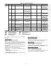
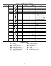
generated if the one of the following configuration errors is
detected by the control. The “nn” refers to the error code listed
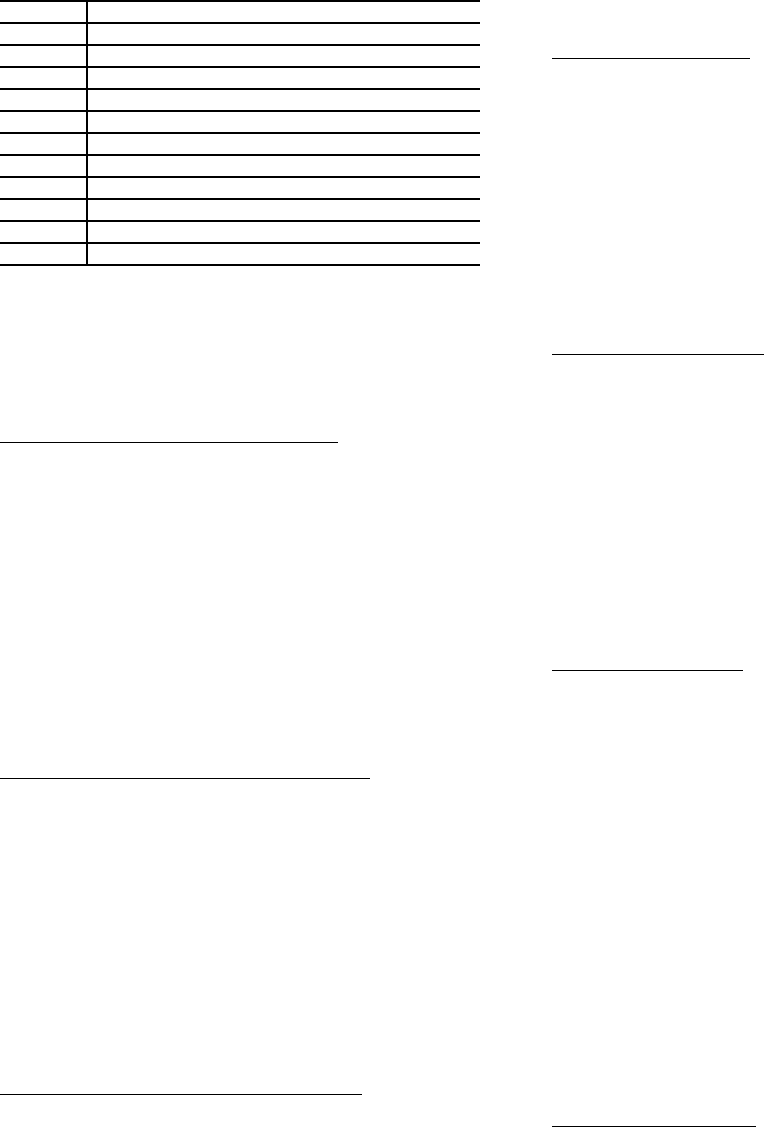
in Table 52.
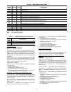
Table 52 — Service Maintenance Alert Codes
Action to be Taken — None.
Reset Method — Manual, after the service has been completed.
Possible Causes — If the Sr-01, 02, or 03 conditions are
encountered, check the following items:
• sensor wiring to the Main Base Board
• sensor for accuracy
Compressor Motor Temperature Too High
Alarm 132-01 — Circuit A (A1.01)
Alarm 133-01 — Circuit B (B1.01)
Criteria for Trip — The alarm criteria are checked when the
compressor is ON. This alarm will be generated if:
• The temperature is greater than 245 F (118 C) and it has
been greater than 212 F (100 C) for 10 consecutive seconds.
• The compressor temperature is greater than 232 F (111 C)
for 90 seconds (but less than 250 F [120 C]).
Action to be Taken — The circuit shuts down immediately.
Reset Method — Manual
Possible Causes — If this condition is encountered, check the
following items:
• faulty wiring and loose plugs
• faulty CPM board
Compressor Motor Temperature Out of Range
Alarm 132-02 — Circuit A (A1.02)
Alarm 133-02 — Circuit B (B1.02)
Criteria for Trip — The alarm criterion is checked when the
compressor is ON. This alarm will be generated if: the temper-
ature is greater than 245 F (118 C) and it has NOT been greater
than 212 F (100 C) for 10 consecutive seconds.
Action to be Taken — The compressor will be stopped.
Reset Method — Manual
Possible Causes — If this condition is encountered, check the
following items:
• faulty compressor temperature thermistor
• faulty wiring and loose plugs
• faulty CPM board
Compressor High Pressure Switch Protection
Alarm 132-03 — Circuit A (A1.03)
Alarm 133-03 — Circuit B (B1.03)
Criteria for Trip — The alarm criterion is checked when the
compressor is ON. This alarm will be generated if the circuit
high-pressure switch (HPS) opens for more than 2 seconds.
The CPM board monitors the HPS switch.
Action to be Taken — The compressor will be stopped.
Reset Method — Manual (reset button on switch)
Possible Causes — If this condition is encountered, check the
following items:
• loss of condenser water flow
• condenser pump failure
• compressor operating beyond the operation envelope
• faulty high pressure switch or wiring
• faulty CPM board
Compressor Overcurrent
Alarm 132-04 — Circuit A (A1.04)
Alarm 133-04 — Circuit B (B1.04)
Criteria for Trip — The alarm criterion is checked when the
compressor is ON. This alarm will be generated if the CPM
board detects a motor current greater than 93% MTA (must
trip amps) and less than 2 times that for more than 1.7 seconds.
Action to be Taken — The compressor will be stopped.
Reset Method — Manual
Possible Causes — If this condition is encountered, check the
following items:
• Compressor operating beyond the operation envelope.
• Incorrect MTA setting.
Compressor Locked Rotor
Alarm 132-05 — Circuit A (A1.05)
Alarm 133-05 — Circuit B (B1.05)
Criteria for Trip — The alarm criterion is checked during
start-up when the compressor is ON. This alarm will be gener-
ated if the CPM board detects a high motor current compared
with the MTA (must trip amps) setting for more than 450 ms.
Action to be Taken — The compressor will be stopped.
Reset Method — Manual
Possible Causes — If this condition is encountered, check the
following items:
• compressor mechanical failure
• unloader slide valve failure
• compressor motor failure
Compressor Phase Loss
Alarm 132-06 — Circuit A L1 (A1.06)
Alarm 133-06 — Circuit B L1 (B1.06)
Alarm 132-07 — Circuit A L2 (A1.07)
Alarm 133-07 — Circuit B L2 (B1.07)
Alarm 132-08 — Circuit A L3 (A1.08)
Alarm 133-08 — Circuit B L3 (B1.08)
Criteria for Trip — The alarm criteria are checked during
startup when the compressor is ON. This alarm will be gener-
ated if:
• The current unbalance on any of the 3 phases is greater than
48% for more than 1 second continuously during start-up.
• The current unbalance on any of the 3 phases is greater than
48% for more than 2 seconds continuously during runtime.
Action to be Taken — The compressor will be stopped.
Reset Method — Manual
Possible Causes — If this condition is encountered, check the
following items:
• power failure
• blown fuse or tripped circuit breaker
• power wiring errors or loose terminals
Compressor Low Current
Alarm 132-09 — Circuit A (A1.09)
Alarm 133-09 — Circuit B (B1.09)
Criteria for Trip — The alarm criteria are checked when the
compressor is ON. This alarm will be generated if:
• The current is less than 15% MTA on all three legs for more
than 1 second for Wye-Delta start units.
• If the current is less than 15% of MTA on all three legs for
more than 1 second for direct start units.
CODE DESCRIPTION
Sr.01 Circuit A Loss of Refrigerant Charge
Sr.02 Circuit B Loss of Refrigerant Charge
Sr.04 Water Loop Size Warning
Sr.05 Air Exchanger Cleanliness Warning
Sr.06 Cooler Pump 1 Servicing Required
Sr.07 Cooler Pump 2 Servicing Required
Sr.08 Condenser Pump 1 Servicing Required
Sr.09 Condenser Pump 2 Servicing Required
Sr.10 Water Filter Servicing Required
Sr.11 Compressor A Oil Filter Servicing Required
Sr.12 Compressor B Oil Filter Servicing Required