


40
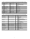
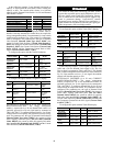
In the following example, 2-step demand limit based on
capacity is desired with the first switch closure limiting the
capacity to 60%. The second switch closure is to limit the
capacity to 40%. Demand Limit Switch 1 is 60% and Demand
Limit Switch 2 is 40%.
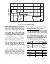
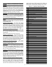
Switch Controlled (Current Based)
— If using 2-step de-
mand limit control, an energy management module must be
installed. One-step demand limit control does not require the
energy management module. Four parameters for 1-step switch
control must be configured. For 2-step control, five parameters
must be configured. The parameters are: the type of Demand
Limit Selection (Demand Limit Type Select, DMDC), the
setting for Switch Limit Set Point 1 (Switch Limit Setpoint 1,
DLS1), the setting for Switch Limit Set Point 2 (Switch Limit
Setpoint 2, DLS2), the Current Limit Select (Current Limit
Select, CUR.S), and the Compressor Current limit at 100%
signal, (Current Limit at 100%, CUR.F).
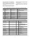
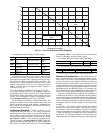
To configure this option with the Touch Pilot display:
To configure this option with the Navigator™ display:
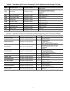
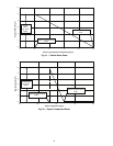
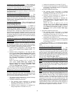
EXTERNALLY POWERED (4 to 20 mA) CAPACITY
BASED DEMAND LIMIT — The energy management
module is required for 4 to 20 mA demand limit control. An
externally powered 4 to 20 mA signal must be connected to
TB6-1 and TB6-2. To configure demand limit for 4 to 20 mA
control based on unit capacity, four parameters must be config-
ured. The parameters are: the type of Demand Limit Selection
(Demand Limit Type Select, DMDC), the current at which
100% capacity limit takes place (mA For 100% Demand
Limit, DMMX), the current at which 0% capacity limit takes
place (mA For 0% Demand Limit, DMZE), and the Current
Limit Selection (Current Limit Select, CUR.S).
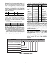
To configure this option with the Touch Pilot™ display:
To configure this option with the Navigator display:
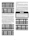
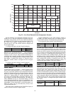
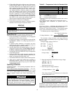
In the following example, a 4 mA signal is Demand Limit
100% and a 20 mA Demand Limit signal is 0%. The 4 to
20 mA signal is connected to TB6-1 and TB6-2. The demand
limit is a linear interpolation between the two values entered. In
Fig. 24, if the machine receives a 12 mA signal, the machine
controls will limit the capacity to 50%.
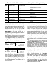
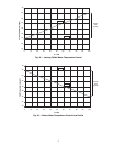
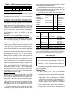
EXTERNALLY POWERED (4 to 20 mA) CURRENT
BASED DEMAND LIMIT — The energy management
module is required for 4 to 20 mA demand limit control. An
externally powered 4 to 20 mA signal must be connected to
TB6-1 and TB6-2. To configure demand limit for 4 to 20 mA
control based on compressor current, five parameters must be
configured. The parameters are: the type of Demand Limit
Selection (Demand Limit Type Select, DMDC), the current at
which 100% capacity limit takes place (mA For 100%
Demand Limit, DMMX), the current at which 0% capacity
limit takes place (mA For 0% Demand Limit, DMZE), the
Current Limit Selection (Current Limit Select, CUR.S), and
the Compressor Current limit at 100% signal (Current Limit
at 100%, CUR.F).
To configure this option with the Touch Pilot display:
TOUCH PILOT DISPLAY NAVIGATOR DISPLAY
Display Name Value Item Value
Demand Limit Type Select 1 DMDC SWITCH
Switch Limit Setpoint 1 60% DSL1 60%
Switch Limit Setpoint 2 40% DSL2 40%
Current Limit Select No CUR.S NO
DISPLAY NAME PATH
LINE
NO.
VALUE
Demand Limit
Type Select
Config USER 24
1 (Switch Control)
Default = 0
(None)
Switch Limit
Setpoint 1
Setpoints SETPOINT 33 Default = 100%
Switch Limit
Setpoint 2
Setpoints SETPOINT 34
(Not required
for 1-Step)
Default = 100%
Current Limit
Select
Config USER 30
Ye s
Default = No
Current Limit
at 100%
Config USER 31
Default =
2000.0 Amps
ITEM ITEM EXPANSION PATH VALUE
DMDC
Demand Limit
Select
Configuration RSET
SWITCH
Default =
NONE
DSL1
Switch Limit
Setpoint 1
Setpoints MISC
Default =
100%
DSL2
Switch Limit
Setpoint 2
Setpoints MISC
(Not required
for 1-Step)
Default =
100%
CUR.S
Current Limit
Select
Configuration OPTN
NO
Default: NO
CUR.F
Current Limit
at 100%
Configuration OPTN
Default =
2000
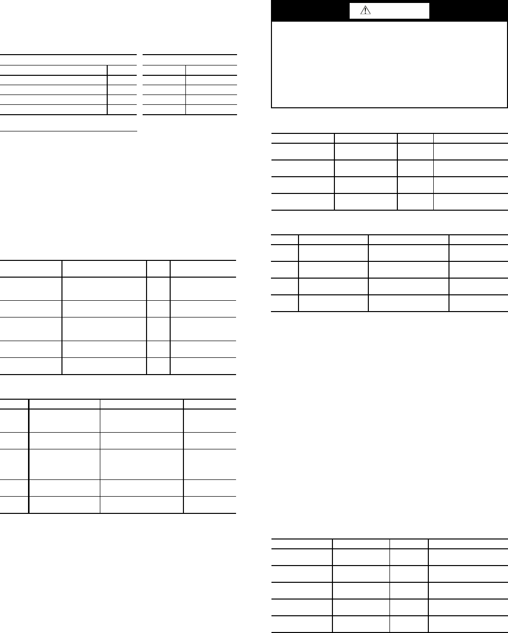
CAUTION
Care should be taken when interfacing with other control
systems due to possible power supply differences such as a
full wave bridge versus a half wave rectification. Connec-
tion of control devices with different power supplies may
result in permanent damage. ComfortLink™ controls
incorporate power supplies with half wave rectification. A
signal isolation device should be utilized if the signal gen-
erator incorporates a full wave bridge rectifier.
DISPLAY NAME PATH LINE NO. VALUE
Demand Limit
Type Select
Config USER 24
2 (4-20mA Control)
Default = 0 (None)
mA For 100%
Demand Limit
Config USER 28 Default = 0.0 mA
mA For 0%
Demand Limit
Config USER 29 Default = 10.0 mA
Current Limit
Select
Config USER 30
No
Default = No
ITEM ITEM EXPANSION PATH VALUE
DMDC
Demand Limit
Select
Configuration RSET
4-20MA INPUT
Default = NONE
DMMX
mA for 100%
Demand Lim
Configuration RSET
Default =
0.0 mA
DMZE
mA for 0%
Demand Limit
Configuration RSET
Default =
10.0 mA
CUR.S
Current Limit
Select
Configuration OPTN
NO
Default: NO
DISPLAY NAME PATH LINE NO. VALUE
Demand Limit
Type Select
Config USER 24
2 (4-20mA Control)
Default = 0 (None)
mA For 100%
Demand Limit
Config USER 28 Default = 0.0 mA
mA For 0%
Demand Limit
Config USER 29 Default = 10.0 mA
Current Limit
Select
Config USER 30
Ye s
Default = No
Current Limit
at 100%
Config USER 31 Default = 2000.0 Amps