


18
Carrier Comfort Network
®
(CCN) Interface —
All 30XW units can be connected to a CCN system, if desired.
The communication bus wiring is a shielded, 3-conductor cable
with drain wire and is field supplied and installed. The system
elements are connected to the communication bus in a daisy
chain arrangement. The positive pin of each system element
communication connector must be wired to the positive pins of
the system elements on either side of it. The negative and sig-
nal ground pins of each system element must also be wired in
the same manner. Wiring connections for CCN should be made
at TB3. Consult the CCN Contractor’s Manual for further in-
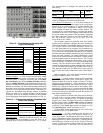
formation. See Fig. 14.
NOTE: Conductors and drain wire must be 20 AWG (Ameri-
can Wire Gage) minimum stranded, tinned copper. Individual
conductors must be insulated with PVC, PVC/nylon, vinyl,
Teflon, or polyethylene. An aluminum/polyester 100% foil
shield and an outer jacket of PVC, PVC/nylon, chrome vinyl,
or Teflon with a minimum operating temperature range of
–20 C to 60 C is required. See Table 11 for recommended wire
manufacturers and part numbers.
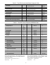
Table 11 — CCN Communication Bus Wiring
It is important when connecting to a CCN communication
bus that a color-coding scheme be used for the entire network
to simplify the installation. It is recommended that red be used
for the signal positive, black for the signal negative, and white
for the signal ground. Use a similar scheme for cables contain-
ing different colored wires.
At each system element, the shields of its communication
bus cables must be tied together. If the communication bus is
entirely within one building, the resulting continuous shield
must be connected to a ground at one point only. If the commu-
nication bus cable exits from one building and enters another,
the shields must be connected to grounds at the lightning
suppressor in each building where the cable enters or exits the
building (one point per building only). To connect the unit to
the network:
1. Turn off power to the control box.
2. Cut the CCN wire and strip the ends of the red (+), white
(ground), and black (–) conductors. (Substitute appropri-
ate colors for different colored cables.)
3. Connect the red wire to (+) terminal on TB3 of the plug,
the white wire to COM terminal, and the black wire to the
(–) terminal.
4. The RJ14 CCN connector on TB3 can also be used, but is
only intended for temporary connection (for example, a
laptop computer running Service Tool).
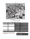
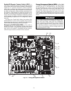
Remote Alarm and Alert Relays — The 30XW
chiller can be equipped with a remote alert and remote alarm
annunciator contacts. Both relays connected to these contacts
must be rated for a maximum power draw of 10 va sealed,
25 va inrush at 24 volts. The alarm relay, indicating that the
complete unit has been shut down, can be connected to TB5-12
and TB5-13. Refer to unit wiring diagrams. For an alert relay,
indicating that at least 1 circuit is off due to the alert, a field-
supplied and installed relay must be connected between MBB-
J3-CH25-3 and TB5-13. The action of the alarm and alert re-
lays can be reversed from normally open to normally closed by
using the Reverse Alarms Relay configuration (Reverse
Alarms Relay, RV.AL).
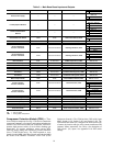
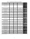
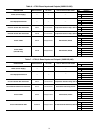
CONFIGURATION
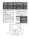
Touch Pilot™ Operation Configuration
Tables —
The Touch Pilot display operation is controlled by
configuration information entered in the following configura-
tion tables. These tables are accessible by using Network Ser-
vice Tool or ComfortVIEW™ software. The tables are the
CtrlID (Controller Identification) configuration table and the
USERCONF (User Configuration) table. See Tables 12 and 13.
NOTE: Always perform an Upload to obtain the latest config-
uration before making configuration table changes.
MANUFACTURER
PART NUMBER
Regular Wiring Plenum Wiring
Alpha 1895 —
American A21451 A48301
Belden 8205 884421
Columbia D6451 —
Manhattan M13402 M64430
Quabik 6130 —
IMPORTANT: A shorted CCN bus cable will prevent
some routines from running and may prevent the unit
from starting. If abnormal conditions occur, discon-
nect the CCN bus. If conditions return to normal,
check the CCN connector and cable. Run new cable if
necessary. A short in one section of the bus can cause
problems with all system elements on the bus.
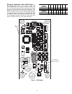
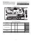
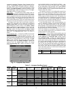
Fig. 14 — ComfortLink™ CCN Communication Wiring
(+) (COM) (-) SHIELD
CCN
RED
WHT
BLK
CCNLEN
(+) (COM) (-) SHIELD
CCN
RED
WHT
BLK
CCNLEN
TO NEXT
DEVICE
(+) (COM) (-) SHIELD
CCN
RED
WHT
BLK
CCN
LEN
SHIELD
LEGEND
CCN — Carrier Comfort Network
®
LEN — Local Equipment Network
a30-4706