


64
Oil Charge
— When additional oil or a complete charge is
required it must meet the following specifications:
• Manufacturer . . . . . . . . . . . . . . . . . . . . . Emkarate RL220XL
• Oil Type . . . . . . . . . . . . . . . . . . . Inhibited polyolester-based
synthetic compressor lubricant for use with screw compressors.
• ISO Viscosity Grade . . . . . . . . . . . . . . . . . . . . . . . . . . . . . 220
Do not reuse drained oil or any oil that has been exposed to
the atmosphere.
Oil is available in the following quantities from your local
Carrier representative:
If unsure if there is low oil charge in the system, follow the
steps below:
1. If the unit shuts off repeatedly from a low oil level alert it
may be an indication of inadequate oil charge; however, it
could also indicate that the oil is not being recovered from
the low-side of the system.
2. Begin running the unit at full load for 1
1
/
2
hours. Use the
manual Test Mode feature of Service Test if the unit does
not normally run at full load.
NOTE: An adequate load must be available.
3. After running the unit for 1
1
/
2
hours at full load, allow the
unit to restart and run normally. If low oil alarms persist,
continue with the following steps.
4. Close the liquid line service valve and place a pressure
gage on top of the cooler. Enable the Service Test feature
and turn the Enable/Off/Remote switch to the enable po-
sition. Start the desired circuit by turning it on under the
TEST function: CP.A for compressor A, CP.B for com-
pressor B, or CP.C for compressor C.
5. When the compressor starts successfully observe the
cooler pressure when the pressure reads 10 psig
(68.9 kPa), turn the Emergency Switch (SW2) to the OFF
position. The compressor should stop.
6. Open the liquid line service valve and allow the unit to
restart normally. If low oil level alarms persist, continue
with the following steps.
7. If none of the previous steps were successful, the unit is
low on oil charge. Add oil to the oil separator using the
1
/
4
in. access fitting that the discharge pressure transducer
is mounted to.
8. To facilitate the oil charging process, ensure that the unit
is not running when adding oil. The system is under pres-
sure even when the unit is not running, so it is necessary
to use a suitable pump to add oil to the system.
9. Using a suitable pump, add
1
/
2
gal (1.9 l) of oil to the
system. Continue adding oil in
1
/
2
gal (1.9 l) increments
until the problem is resolved, up to a maximum of 1.5 gal
(5.7 l). If it is necessary to add factory oil charge levels to
the system contact your local Carrier representative.
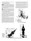
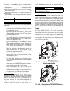
Oil Filter Maintenance
— Each circuit has one oil filter locat-
ed externally to the compressor. Oil line pressure drop is
monitored by the control. Oil line pressure drop is calculated
by subtracting oil pressure (OP) from discharge pressure (DP).
If the oil line pressure drop exceeds 30 psi (206.8 kPa) for
5 minutes the control will generate a High Oil Filter Pressure
Drop alert. The High Oil Filter Pressure Drop alert will
not shut down the compressor, but instead indicates that the
oil filter is dirty. If oil pressure line losses exceed 50 psi
(344.7 kPa) then the control will shut down the circuit on
Maximum Oil Filter Differential Pressure Failure.
Replacing the Oil Filter
— Close the oil line ball valve locat-
ed in front of the oil filter. Connect a charging hose to the
1
/
4
-in.
access fitting port located downstream of the valve and bleed
off oil trapped between the service valve and the oil solenoid
valve. A quart of oil is typically what is removed during this
process. Remove the charging hose. Unscrew the nuts from
both ends of the oil filter and remove the oil filter. Remove the
protective caps from the new oil filter and install, being careful
not to lose or damage the new O-ring located on the new oil fil-
ter. Draw a vacuum at the Schrader port. Remove the charging
hose and open the oil line ball valve. Check both fittings for
leaks.
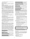
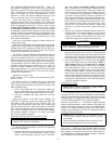
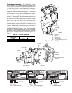
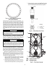
Cooler
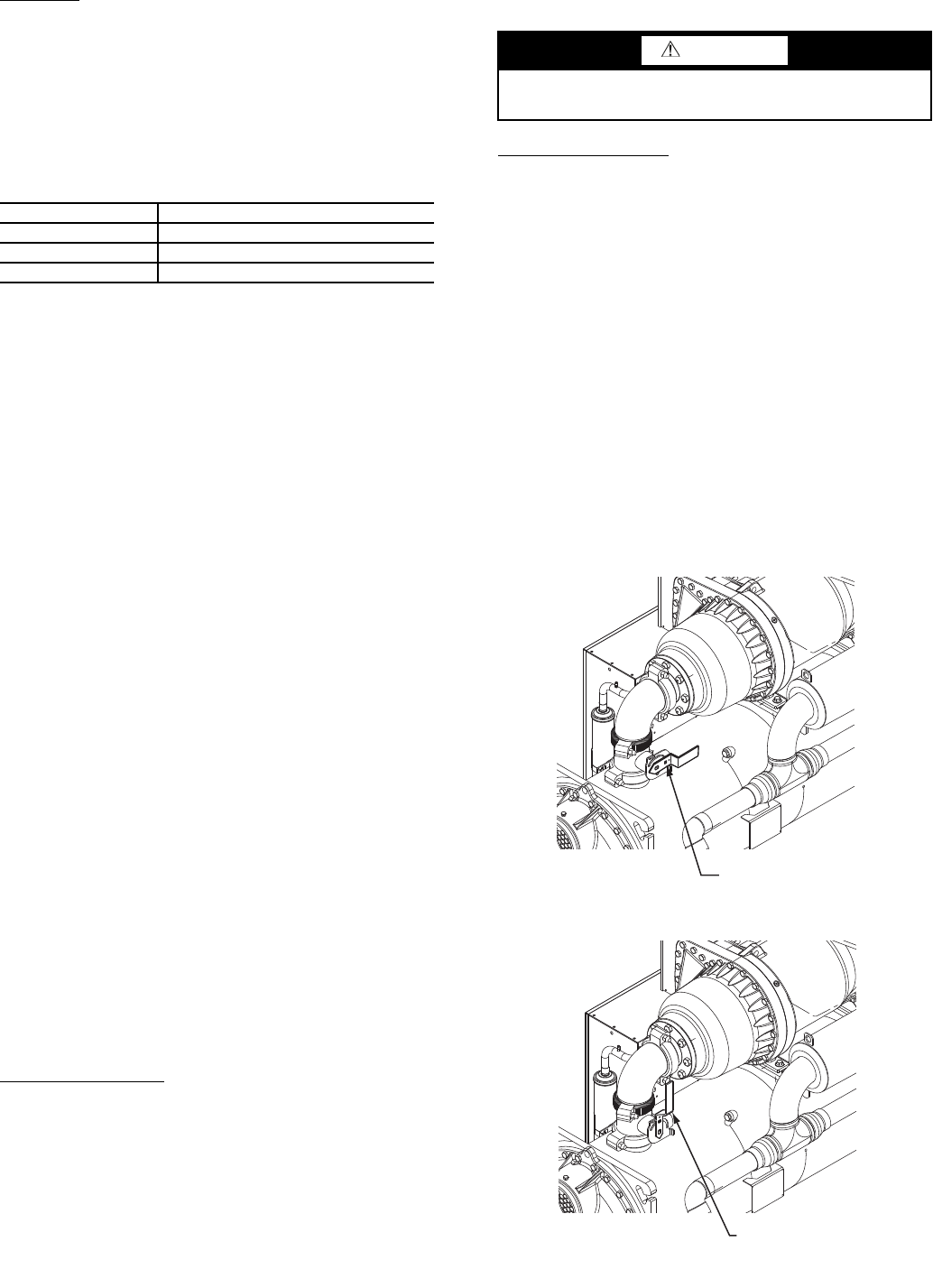
SUCTION SERVICE VALVE — The suction service valve
is a factory-installed option for 30XW units. It is located in the
suction outlet of the cooler. The suction service valve is bolted
between the cooler outlet and the suction flange piping. The
suction service valve shaft has a locking device located on the
shaft to lock the valve in either a fully open position or a fully
closed position. The locking device must be pulled out prior to
moving the valve handle to a fully open or a fully closed posi-
tion. See Fig. 47A and 47B.
QUANTITY TOTALINE PART NO.
1 Quart P903-2325
1 Gallon P903-2301
5 Gallon P903-2305
CAUTION
Compressor oil is pressurized. Use proper safety precau-
tions when relieving pressure.
CLOSED AND UNLOCKED
SUCTION SERVICE VALVE
OPENED AND LOCKED
SUCTION SERVICE VALVE
Fig. 47A — Suction Service Valve Locking Device,
Closed and Unlocked
Fig. 47B — Suction Service Valve Locking Device,
Open and Locked
A30-4843
A30-4844