


ESAI Initialization Examples
DSP56364 24-Bit Digital Signal Processor Users Manual, Rev. 2
6-50 Freescale Semiconductor
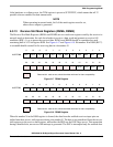
configured as GPIO. If a port pin [i] is configured as a GPIO input, then the corresponding PD[i] bit
reflects the value present on this pin. If a port pin [i] is configured as a GPIO output, then the value written
into the corresponding PD[i] bit is reflected on this pin. If a port pin [i] is configured as disconnected, the
corresponding PD[i] bit is not reset and contains undefined data.
6.6 ESAI Initialization Examples
6.6.1 Initializing the ESAI Using Individual Reset
• The ESAI should be in its individual reset state (PCRC = $000 and PRRC = $000). In the individual
reset state, both the transmitter and receiver sections of the ESAI are simultaneously reset. The
TPR bit in the TCR register may be used to reset just the transmitter section. The RPR bit in the
RCR register may be used to reset just the receiver section.
• Configure the control registers (TCCR, TCR, RCCR, RCR) according to the operating mode, but
do not enable transmitters (TE5–TE0 = $0) or receivers (RE3–RE0 = $0). It is possible to set the
interrupt enable bits which are in use during the operation (no interrupt occurs).
• Enable the ESAI by setting the PCRC register and PRRC register bits according to pins which are
in use during operation.
• Write the first data to be transmitted to the transmitters which are in use during operation.
This step is needed even if DMA is used to service the transmitters.
• Enable the transmitters and receivers.
• From now on ESAI can be serviced either by polling, interrupts, or DMA.
Operation proceeds as follows:
• For internally generated clock and frame sync, these signals are active immediately after ESAI is
enabled (step 3 above).
• Data is received only when one of the receive enable (REx) bits is set and after the occurrence of
frame sync signal (either internally or externally generated).
• Data is transmitted only when the transmitter enable (TEx) bit is set and after the occurrence of
frame sync signal (either internally or externally generated). The transmitter outputs remain
tri-stated after TEx bit is set until the frame sync occurs.
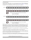
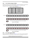
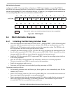
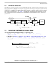
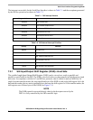
11109876543210
X:$FFFFBD PD11 PD10 PD9 PD8 PD7 PD6 PD5 PD4 PD3 PD2 PD1 PD0
23 22 21 20 19 18 17 16 15 14 13 12
Reserved bit - read as zero; should be written with zero for future compatibility.
Figure 6-21 PDRC Register