


DSP56364 24-Bit Digital Signal Processor Users Manual, Rev. 2
Freescale Semiconductor 7-1
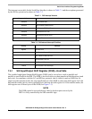
7 Serial Host Interface
7.1 Introduction
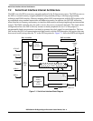
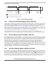
The Serial Host Interface (SHI) is a serial I/O interface that provides a path for communication and
program/coefficient data transfers between the DSP and an external host processor. The SHI can also
communicate with other serial peripheral devices. The SHI can interface directly to either of two
well-known and widely used synchronous serial buses: the Freescale Serial Peripheral Interface (SPI) bus
and the Philips Inter-Integrated-circuit Control (I
2
C) bus. The SHI supports either the SPI or I
2
C bus
protocol, as required, from a slave or a single-master device. To minimize DSP overhead, the SHI supports
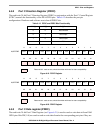
single-, double-, and triple-byte data transfers. The SHI has a 10-word receive FIFO that permits receiving
up to 30 bytes before generating a receive interrupt, reducing the overhead for data reception.
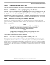
When configured in the SPI mode, the SHI can:
• Identify its slave selection (in Slave mode)
• Simultaneously transmit (shift out) and receive (shift in) serial data
• Directly operate with 8-, 16- and 24-bit words
• Generate vectored interrupts, separately for receive and transmit events, and update status bits
• Generate a separate vectored interrupt in the event of a receive exception
• Generate a separate vectored interrupt in the event of a bus-error exception
• Optionally trigger DMA interrupts to service the transmit and receive events
• Generate the serial clock signal (in Master mode)
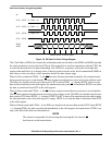
When configured in the I
2
C mode, the SHI can:
• Detect/generate start and stop events
• Identify its slave (ID) address (in Slave mode)
• Identify the transfer direction (receive/transmit)
• Transfer data byte-wise according to the SCL clock line
• Generate ACK signal following a byte receive
• Inspect ACK signal following a byte transmit
• Directly operate with 8-, 16- and 24-bit words
• Generate vectored interrupts separately for receive and transmit events and update status bits
• Generate a separate vectored interrupt in the event of a receive exception
• Generate a separate vectored interrupt in the event of a bus error exception
• Optionally trigger DMA interrupts to service the transmit and receive events
• Generate the clock signal (in Master mode)