


I
2
C Bus Characteristics
DSP56364 24-Bit Digital Signal Processor Users Manual, Rev. 2
Freescale Semiconductor 7-19
the slave device is ready for the next byte transfer. The SHI supports this feature when operating as a
master device and will wait until the slave device releases the SCL line before proceeding with the data
transfer.
7.6.2 I
2
C Data Transfer Formats
I
2
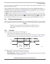
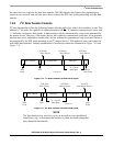
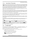
C bus data transfers follow the following format: after the start event, a slave device address is sent. This
address is 7 bits wide, the eighth bit is a data direction bit (R/W); ‘0’ indicates a transmission (write), and
‘1’ indicates a request for data (read). A data transfer is always terminated by a stop event generated by
the master device. However, if the master device still wishes to communicate on the bus, it can generate
another start event, and address another slave device without first generating a stop event (this feature is
not supported by the SHI when operating as an I
2
C master device). This method is also used to provide
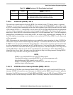
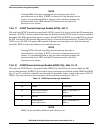
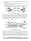
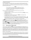
indivisible data transfers. Various combinations of read/write formats are illustrated in Figure 7-10 and
Figure 7-11.
Figure 7-10 I
2
C Bus Protocol For Host Write Cycle
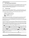
Figure 7-11 I
2
C Bus Protocol For Host Read Cycle
NOTE
The first data byte in a write-bus cycle can be used as a user-predefined
control byte (e.g., to determine the location to which the forthcoming data
bytes should be transferred).
SAA0Slave Address
R/W
S, PA
Start
Start or
Event Stop Event
Slave Device
ACK from
Slave Device
ACK from
Slave Device
ACK from
N = 0 to M
Data Bytes
First Data Byte Data Byte
AA0425 new
SAA1Slave Address
R/W
P 1
Start Stop
Event Event
Slave Device
ACK from
Master Device
ACK from
No ACK
Data Byte
N = 0 to M
Data Bytes
Last Data Byte
from Master Device
AA0426 new