


Audio Processor Architecture
DSP56364 24-Bit Digital Signal Processor Users Manual, Rev. 2
Freescale Semiconductor 1-3
— Very low-power CMOS design, fully static design with operating frequencies down to DC.
— STOP and WAIT low-power standby modes.
• On-chip Memory Configuration
— 1.5K × 24 Bit Y-Data RAM.
—1K × 24 Bit X-Data RAM.
—8K × 24 Bit Program ROM.
— 0.5K × 24 Bit Program RAM and 192 × 24 Bit Bootstrap ROM.
— 0.75K × 24 Bit from Y Data RAM can be switched to Program RAM resulting in up to
1.25K × 24 Bit of Program RAM.
• Off-chip memory expansion
— External Memory Expansion Port with 8-bit data bus.
— Off-chip expansion up to 2 × 16M x 8-bit word of Data memory when using DRAM.
— Off-chip expansion up to 2 × 256K x 8-bit word of Data memory when using SRAM.
— Simultaneous glueless interface to SRAM and DRAM.
• Peripheral modules
— Serial Audio Interface (ESAI): up to 4 receivers and up to 6 transmitters, master or slave. I
2
S,
Sony, AC97, network and other programmable protocols. Unused pins of ESAI may be used
as GPIO lines.
— Serial Host Interface (SHI): SPI and I
2
C protocols, multi master capability, 10-word receive
FIFO, support for 8, 16 and 24-bit words.
— Four dedicated GPIO lines.
• 100-pin plastic TQFP package.
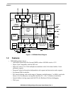
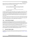
1.3 Audio Processor Architecture
This section defines the DSP56364 audio processor architecture. The audio processor is composed of the
following units:
• The DSP56300 core is composed of the Data ALU, Address Generation Unit, Program Controller,
Instruction-Cache Controller, DMA Controller, PLL-based clock oscillator, Memory Module
Interface, Peripheral Module Interface and the On-Chip Emulator (OnCE). The DSP56300 core is
described in the document DSP56300 24-Bit Digital Signal Processor Family Manual, Motorola
publication DSP56300FM.
• Memory modules.
• Peripheral modules. The SHI, ESAI and GPIO peripheral are described in this document.
See Figure 1-1 for the block diagram of the DSP56364.