


Bootstrap Program
DSP56364 24-Bit Digital Signal Processor Users Manual, Rev. 2
4-4 Freescale Semiconductor
address to start loading the program words and then a 24-bit word for each program word
to be loaded. The program words will be stored in contiguous PRAM memory locations
starting at the specified starting address. After reading the program words, program
execution starts from the same address where loading started.
Mode E Same as mode 5, except the SHI interface operates in the I
2
C slave mode with clock freeze
enabled.
Mode F Same as mode 5, except the SHI interface operates in the I
2
C slave mode with clock freeze
disabled (compatible to DSP56000 family).
4.4 Bootstrap Program
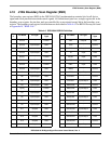
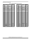
The bootstrap program is factory-programmed in an internal 192 word by 24-bit bootstrap ROM located
in program memory space at locations $FF0000–$FF00BF. The bootstrap program can load any program
RAM segment from an external byte-wide EPROM or the SHI. The bootstrap program described here, and
listed in Appendix A, is a default, which may be modified or replaced by the customer.
On exiting the Reset state, the DSP56364 does the following:
1. Samples the MODA, MODB, and MODD signal lines
2. Loads their values into bits MA, MB, and MD in the OMR
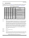
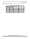
The contents of the MA, MB, MC, and MD bits determine which bootstrap mode the DSP56364 enters.
See Table 4-1 for a tabular description of the mode bit settings for the operating modes.
The bootstrap program options can be invoked at any time by setting the appropriate MA, MB, and MD
bits in the OMR and jumping to the bootstrap program entry point, $FF0000. The mode selection bits in
the OMR can be set directly by software.It is recommended to keep the MC bit set to 1.
In bootstrap modes 5, D, E, and F, the bootstrap program expects the following data sequence when
downloading the user program through an external port:
1. Three bytes defining the number of (24-bit) program words to be loaded
2. Three bytes defining the (24-bit) start address to which the user program loads in the DSP56364
program memory
3. The user program (three bytes for each 24-bit program word). The program words will be stored
in contiguous PRAM memory locations starting at the specified starting address.
The three bytes for each data sequence must be loaded with the least significant byte first.
Once the bootstrap program completes loading the specified number of words, it jumps to the specified
starting address and executes the loaded program.
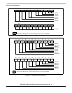
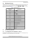
4.5 Interrupt Priority Registers
There are two interrupt priority registers in the DSP56364: IPR-C is dedicated for DSP56300 Core
interrupt sources and IPR-P is dedicated for DSP56364 peripheral interrupt sources. The interrupt priority
registers are shown in Figure 4-2 and Figure 4-3 The Interrupt Priority Level bits are defined in Table 4-2.