


Device Identification (ID) Register
DSP56364 24-Bit Digital Signal Processor Users Manual, Rev. 2
4-8 Freescale Semiconductor
4.7.2 Crystal Range Bit (XTLR) - Bit 15
The Crystal Range (XTLR) bit controls the on-chip crystal oscillator transconductance. The on-chip
crystal oscillator is not used on the DSP56364 since no XTAL pin is available. The XTLR bit is set to zero
during hardware reset in the DSP56364.
4.7.3 XTAL Disable Bit (XTLD) - Bit 16
The XTAL Disable Bit (XTLD) is set to 1 (XTAL disabled) during hardware reset in the DSP56364.
4.7.4 Clock Output Disable Bit (COD) - Bit 19
The Clock Output Disable Bit (COD) is set to 0 during hardware reset. Since no clock output pin is
available in the DSP56364, this bit does not affect the functionality of the clock generator.
4.7.5 PLL Pre-Divider Factor (PD0-PD3) - Bits 20-23
The DSP56364 PLL Pre-Divider factor is set to 1 during hardware reset, i.e. the Pre-Divider Factor Bits
PD0-PD3 in the PLL Control Register (PCTL) are set to $0.
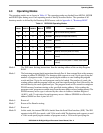
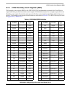
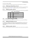
4.8 Device Identification (ID) Register
The Device Identification Register (IDR) is a 24 bit read only factory programmed register used to identify
the different DSP56300 core-based family members. This register specifies the derivative number and
revision number. This information may be used in testing or by software. Table 4-4 shows the ID register
configuration.
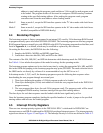
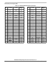
4.9 JTAG Identification (ID) Register
The JTAG Identification (ID) Register is a 32 bit, read only thought JTAG, factory programmed register
used to distinguish the component on a board according to the IEEE 1149.1 standard. Table 4-5 shows the
JTAG ID register configuration.
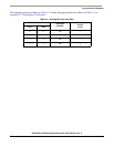
Table 4-4 Identification Register Configuration
23 16 15 12 11 0
Reserved Revision Number Derivative Number
$00 $0 $364
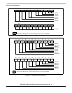
Table 4-5 JTAG Identification Register Configuration
31 28 27 22 21 12 11 1 0
Version Information
Customer Part
Number
Sequence
Number
Manufacturer
Identity
1
0000 000110 0001100100 00000001110 1