


ESAI Programming Model
DSP56364 24-Bit Digital Signal Processor Users Manual, Rev. 2
6-28 Freescale Semiconductor
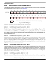
6.3.4.4 RCR ESAI Receiver 3 Enable (RE3) - Bit 3
When RE3 is set and TE2 is cleared, the ESAI receiver 3 is enabled and samples data at the SDO2/SDI3
pin. TX2 and RX3 should not be enabled at the same time (RE3=1 and TE2=1). When RE3 is cleared,
receiver 3 is disabled by inhibiting data transfer into RX3. If this bit is cleared while receiving a data word,
the remainder of the word is shifted in and transferred to the RX3 data register.
If RE3 is set while some of the other receivers are already in operation, the first data word received in RX3
will be invalid and must be discarded.
6.3.4.5 RCR Reserved Bits - Bits 4-5, 17-18
These bits are reserved. They read as zero, and they should be written with zero for future compatibility.
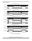
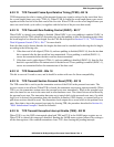
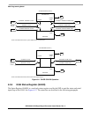
6.3.4.6 RCR Receiver Shift Direction (RSHFD) - Bit 6
The RSHFD bit causes the receiver shift registers to shift data in MSB first when RSHFD is cleared or
LSB first when RSHFD is set (see Figure 6-13 and Figure 6-14).
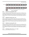
6.3.4.7 RCR Receiver Word Alignment Control (RWA) - Bit 7
The Receiver Word Alignment Control (RWA) bit defines the alignment of the data word in relation to the
slot. This is relevant for the cases where the word length is shorter than the slot length. If RWA is cleared,
the data word is assumed to be left-aligned in the slot frame. If RWA is set, the data word is assumed to be
right-aligned in the slot frame.
If the data word is shorter than the slot length, the data bits which are not in the data word field are ignored.
For data word lengths of less than 24 bits, the data word is right-extended with zeroes before being stored
in the receive data registers.
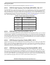
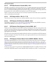
6.3.4.8 RCR Receiver Network Mode Control (RMOD1-RMOD0) - Bits 8-9
The RMOD1 and RMOD0 bits are used to define the network mode of the ESAI receivers according to
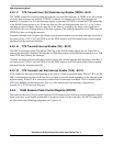
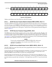
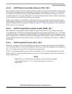
Table 6-10. In the normal mode, the frame rate divider determines the word transfer rate – one word is
transferred per frame sync during the frame sync time slot, as shown in Figure 6-6. In network mode, it is
possible to transfer a word for every time slot, as shown in Figure 6-6. For more details, see Section 6.4,
"Operating Modes".
In order to comply with AC-97 specifications, RSWS4-RSWS0 should be set to 00011 (20-bit slot, 20-bit
word), RFSL and RFSR should be cleared, and RDC4-RDC0 should be set to $0C (13 words in frame).